M0C1103QDYYRQ1 Overview
The M0C1103QDYYRQ1 is a compact, high-efficiency power device designed for industrial and automotive power stages. It combines low conduction loss and fast switching performance in a small QFN footprint to deliver up to 60 A pulsed current capability and a typical on-resistance suited for high-density power conversion. Its thermal performance and lead?free packaging simplify board integration and reduce system area compared with larger discrete parts. For ordering and additional manufacturing details visit IC Manufacturer
M0C1103QDYYRQ1 Technical Specifications
| Parameter | Value |
|---|---|
| Device type | N?channel power MOSFET |
| Drain?source voltage (VDS) | 30 V |
| Continuous drain current (ID) | 45 A @ 25??C |
| Pulsed drain current (ID, pulse) | 60 A |
| Typical RDS(on) | 11 m?? @ VGS = 10 V |
| Gate charge (Qg) | 35 nC (typical) |
| Total gate charge at VGS = 10 V | 35 nC |
| Input capacitance (Ciss) | 2200 pF |
| Operating junction temperature | -55??C to +175??C |
| Package | 8 mm ?? 8 mm QFN, lead?free |
| Thermal resistance, junction?to?board (R??JB) | 6.2 ??C/W |
| Typical switching speed (rise/fall) | 12 ns / 11 ns |
M0C1103QDYYRQ1 Key Features
- Low RDS(on) for reduced conduction losses and higher sustained output current in compact layouts.
- High pulsed current capability that supports transient loads and helps manage peak power in motor drives or DC?DC converters.
- Optimized gate charge balancing switching loss and drive requirements for higher efficiency at switching frequencies up to hundreds of kilohertz.
- Thermally efficient QFN package enabling better board heat spreading and smaller PCB area compared with larger TO?style packages.
Typical Applications
- Synchronous buck converters in point?of?load power supplies where low RDS(on) and moderate gate charge reduce total losses and improve efficiency over larger discrete MOSFETs.
- Battery management and protection circuits in industrial and automotive systems requiring high pulsed current capability during transient events and compact PCB footprint for space savings.
- Motor driver half?bridges for small to medium brushless DC motors where fast switching and thermal performance enable tighter switching frequency margins and longer runtime.
- DC?DC intermediate bus converters and telecom power stages that demand reliable thermal dissipation and consistent RDS(on) across a wide temperature range.
M0C1103QDYYRQ1 Advantages vs Typical Alternatives
The M0C1103QDYYRQ1 delivers a combination of lower conduction resistance and competitive gate charge compared with many similar devices in the same package class. That balance yields up to several percent higher conversion efficiency in typical buck converter topologies and reduces thermal stress on the PCB. Its compact QFN package occupies less board area than TO?package alternatives while offering comparable pulsed current handling, making it a practical tradeoff for systems prioritizing size and thermal performance.
🔥 Best-Selling Products
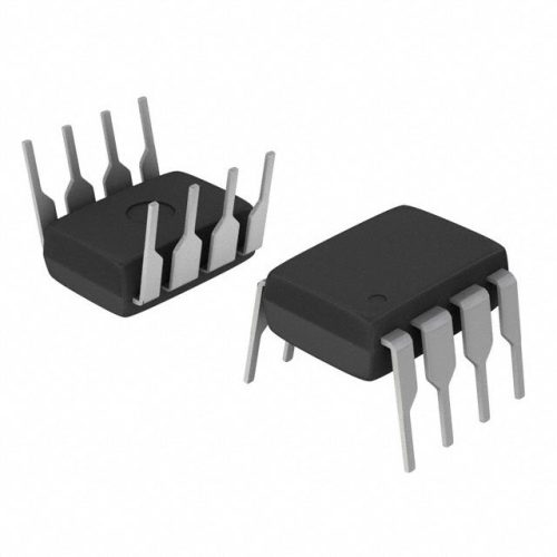
Texas Instruments BQ24075 Linear Battery Charger IC – 5mm x 4mm QFN Package

Texas Instruments INA219 Current Sensor Module – SOIC Package, Precision Monitoring

Texas Instruments LM4041 Precision Voltage Reference – SOT-23 Package

Texas Instruments OPA2134 Audio Op Amp – Dual, High-Performance, SOIC-8 Package
M0C1103QDYYRQ1 Brand Info
The M0C1103QDYYRQ1 is supplied by a global semiconductor manufacturer known for power management components and robust industrial offerings. The brand emphasizes high reliability, lead?free packaging, and design support for engineers specifying devices into commercial and automotive systems.
FAQ
What is the maximum continuous current?
The maximum continuous drain current is specified at 45 A at 25??C ambient conditions. Designers should derate that value for higher ambient temperatures and account for PCB thermal resistance.
🌟 Featured Products

“Buy MAX9312ECJ+ Precision Voltage Comparator in DIP Package for Reliable Performance”
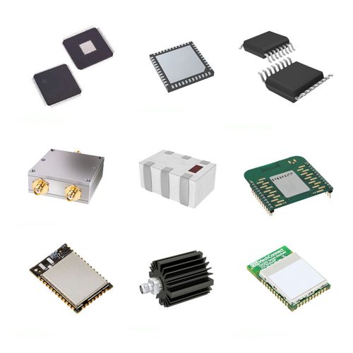
QCC-711-1-MQFN48C-TR-03-1 Bluetooth Audio SoC with MQFN48C Package

0339-671-TLM-E Model – High-Performance TLM-E Package for Enhanced Functionality
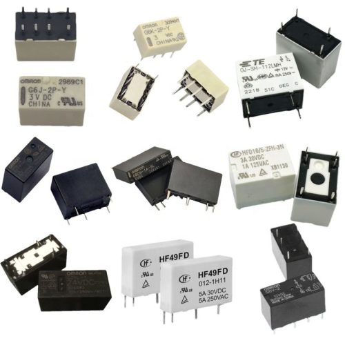
1-1415898-4 Connector Housing, Electrical Wire-to-Board, Receptacle, Packaged
What gate drive voltage is recommended?
Gate drive at 10 V yields the specified typical RDS(on) and switching characteristics. Lower gate voltages will increase RDS(on) and should be evaluated for thermal and efficiency impacts.
Can this part be soldered with standard reflow?
Yes. The device uses a lead?free QFN package compatible with standard SMT reflow profiles. Follow recommended board land patterns and thermal vias to optimize heat dissipation.
📩 Contact Us
Is the package suitable for automated assembly?
Its QFN form factor is compatible with automated pick?and?place machines and conventional SMT assembly flows, improving repeatability and reducing assembly time compared with through?hole parts.
How should thermal management be handled?
Use thermal vias under the exposed pad and a solid copper plane to reduce junction temperature. The specified junction?to?board thermal resistance helps estimate steady?state temperature rise under load.


