


W5500 Arduino Wiring: Complete Guide for Reliable Ethernet Integration
Hardwired Ethernet still wins when stability beats convenience.
Wi-Fi drops. Packets vanish. Latency spikes.
For Arduino projects that must stay online—day and night—the W5500 Ethernet controller is the quiet workhorse behind reliable TCP/IP communication.
This guide focuses on correct wiring, electrical safety, and long-term reliability.
Not shortcuts. Not guesswork.
Just proven design practices that work in real deployments.
Understanding the W5500 Ethernet Controller
The W5500 is a hardware TCP/IP offload chip. That single fact changes everything.
Unlike software stacks, it handles TCP, UDP, ARP, ICMP, and IP internally.
Your Arduino talks SPI. The W5500 talks Ethernet.
Why this matters:
“The best system is the one that keeps working when nobody is watching.”
Why Hardwired TCP/IP Matters
- Deterministic latency
- No RF interference
- Lower CPU and RAM usage
- Stable performance under load
Compared to Wi-Fi or software TCP/IP, the W5500 feels boring—and boring is good.
Hardware Requirements for W5500 Arduino Wiring
Before touching wires, match the hardware correctly.
Supported Arduino Boards
The W5500 works with:
- Arduino UNO / Nano (5V logic, SPI via ICSP)
- Arduino Mega (separate SPI pins)
- 3.3V boards (Due, SAMD, ESP32 as SPI master)
Module vs. Shield
| Option | Pros | Cons |
|---|---|---|
| W5500 Module | Flexible, compact, cheaper | Requires wiring discipline |
| Ethernet Shield | Plug-and-play | Larger, less flexible |
Power Supply Requirements
| Parameter | Typical Value |
|---|---|
| Supply Voltage | 3.3V |
| Average Current | 120–150 mA |
| Peak Current | ~180 mA |
Rule: Never power W5500 from Arduino 3.3V pin on UNO.
Use a dedicated 3.3V regulator.
Electrical and Logic-Level Compatibility
This is where most projects fail.
3.3V vs. 5V Logic
- W5500 I/O is 3.3V tolerant
- SPI inputs accept 5V on many modules due to onboard level shifting
- SPI outputs are 3.3V only
Good news: Most W5500 modules are UNO-safe out of the box.
SPI Clock Speed Trade-offs
| SPI Speed | Result |
|---|---|
| ≤ 8 MHz | Rock solid |
| 12–14 MHz | Usually stable |
| 20+ MHz | Risky on breadboards |
Short wires win. Long wires lose.
Power, Reset, and Startup Reliability
If Ethernet fails randomly, look at reset first.
Reset Pin Best Practice
- RESET must be held low at power-up
- Release only after 3.3V is stable
Recommended Reset Wiring
| Method | Reliability |
|---|---|
| Arduino GPIO reset | Good |
| RC delay reset | Excellent |
| Floating reset | Guaranteed failure |
Symptom of bad reset:
- No link light
- DHCP timeout
- Works only after manual reset
SPI Interface and Pin Connections
SPI is simple—until it isn’t.
Core SPI Signals
| W5500 Pin | Arduino UNO |
|---|---|
| MOSI | D11 |
| MISO | D12 |
| SCK | D13 |
| CS | D10 (recommended) |
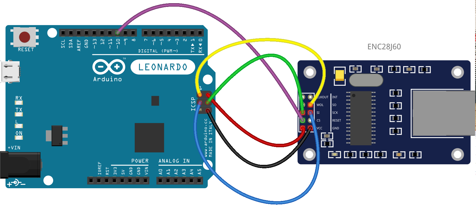
Board-Specific Notes
- UNO / Nano: Use ICSP header for clean signals
- Mega: SPI pins are 50–52, not 11–13
- 3.3V boards: Direct connection, no level shifting
Golden rule:
One SPI bus. Many devices. One CS per device.
Multi-Device SPI Wiring and Chip Select Management
SD cards love to fight.
Safe Multi-SPI Design
- Each device gets its own CS pin
- All unused CS pins pulled HIGH
- Only one CS LOW at any time
| Best Practice | Why It Matters |
|---|---|
| 10k pull-ups on CS | Prevents bus contention |
| Short SPI wires | Clean edges |
| Explicit CS control | Predictable behavior |
Ethernet Connector, Magnetics, and Cabling


Integrated Magnetics
Most W5500 modules include RJ45 + magnetics.
That’s not optional—it’s essential for:
- Signal isolation
- EMI suppression
- Safety compliance
Cable Selection
| Cable | Max Length | Recommendation |
|---|---|---|
| CAT5e | 100 m | ✔ Ideal |
| CAT6 | 100 m | ✔ Better noise margin |
| Cheap flat cable | <10 m | ✖ Avoid |
If the link LED flickers, blame the cable first.
Grounding, Noise, and Signal Integrity
Ethernet is unforgiving.
Grounding Rules
- Common ground between Arduino and W5500
- Star ground if possible
- Avoid breadboards for final designs
Decoupling Strategy
| Capacitor | Placement |
|---|---|
| 0.1 µF | Every VCC pin |
| 10 µF | Near regulator |
| 47–100 µF | Bulk supply |
Noise doesn’t ask permission—it just shows up.
Step-by-Step W5500 Arduino Wiring Example
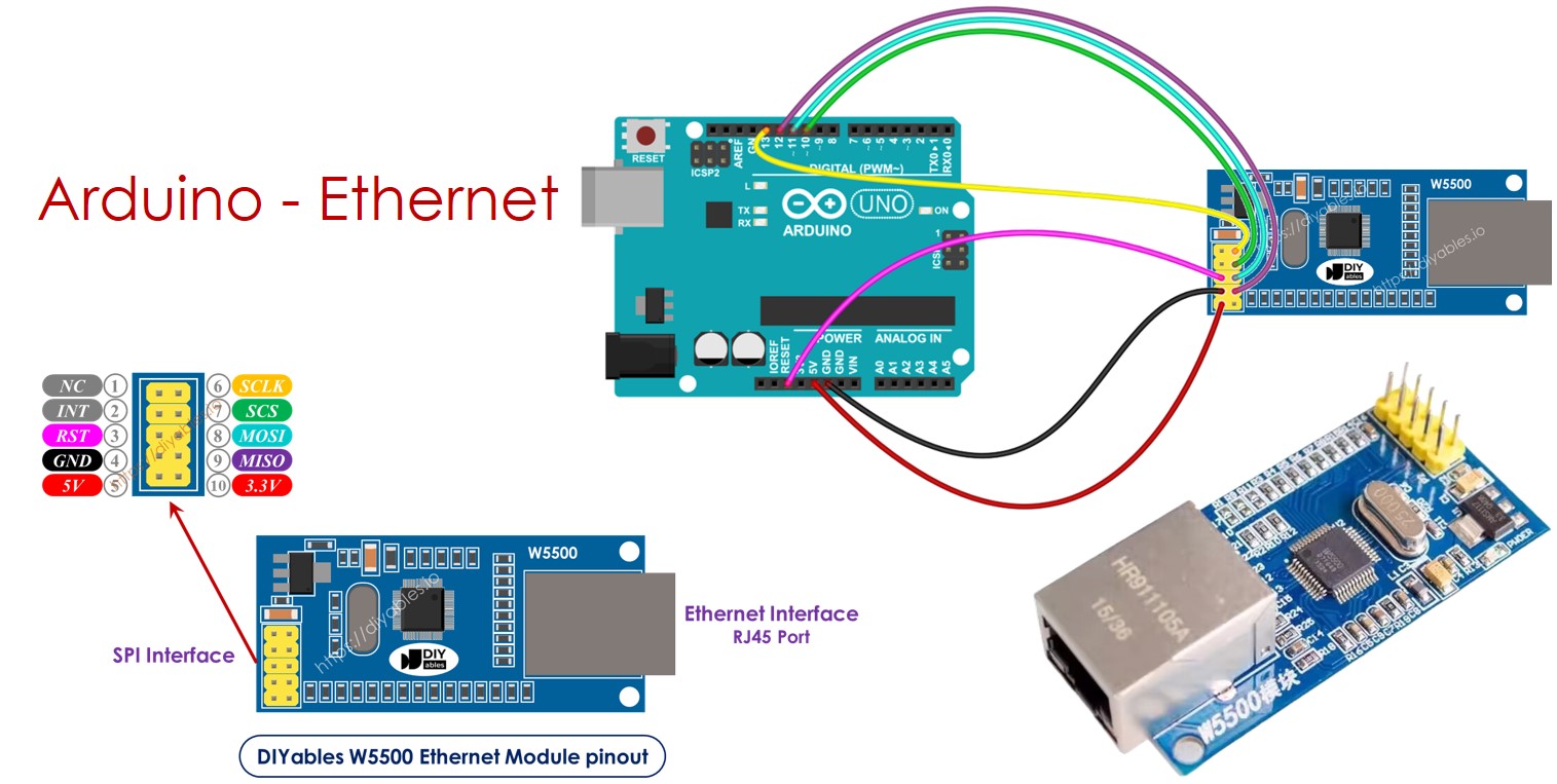
Physical Wiring (UNO / Nano)
| W5500 | Arduino |
|---|---|
| VCC | 3.3V regulator |
| GND | GND |
| MOSI | D11 / ICSP |
| MISO | D12 / ICSP |
| SCK | D13 / ICSP |
| CS | D10 |
| RESET | D9 or RC reset |
First Power-On Checklist
- Link LED ON
- Activity LED blinks on traffic
- No excessive heat
If LEDs stay dark, stop and recheck wiring.
When the W5500 Is the Right Choice
Ethernet isn’t trendy. It’s dependable.
Choose W5500 When You Need:
- 24/7 uptime
- Deterministic latency
- Industrial noise immunity
- Low CPU overhead
Limitations
- No Wi-Fi mobility
- Requires proper power design
- Slightly higher BOM cost
Old proverb, still true:
“Slow is smooth. Smooth is fast.”
Final Thoughts
W5500 Arduino wiring is not difficult.
But it demands respect for power, reset, and signal integrity.
Do it right once:
- Clean SPI routing
- Solid 3.3V power
- Proper reset timing
And the result?
An Ethernet connection that just keeps working—quietly, reliably, endlessly.
If you want, I can also provide:
- A printable wiring checklist
- A fault-isolation flowchart
- A hardened industrial reference design
Just say the word.
