

Understanding Shutdown Pins on ICs: A Practical Guide for Power Control
Power control looks simple on schematics. One pin. One signal. On or off.
In reality, shutdown pins sit at the crossroads of power efficiency, reliability, EMI, and system safety.
Misuse them—and products drain batteries, latch up, or fail compliance tests.
Use them well—and you unlock long battery life, graceful fault handling, and clean power sequencing.
This guide explains shutdown pins practically, deeply, and at a 7th-grade reading level, while still meeting professional engineering expectations.
1. What Is a Shutdown Pin on an IC?
A shutdown pin is a control input that places an IC into a low-power or off state.
Common names include SHDN, EN, ENABLE, ON/OFF, or CTRL.
But names lie. Behavior matters.
Shutdown vs Enable vs Sleep vs Standby
| Term | Typical Meaning | Internal Blocks Disabled | Power Draw |
|---|---|---|---|
| Shutdown | Near-complete power-off | Bias, references, outputs | Lowest |
| Enable | Output gating only | Output stage | Low |
| Sleep | Partial operation | Some logic active | Medium |
| Standby | Fast wake-up | Most logic active | Higher |
Rule of thumb:
“Shutdown saves batteries. Sleep saves time.”
Functional vs Power-Domain Shutdown
- Functional shutdown disables outputs but keeps bias alive
- Power-domain shutdown removes internal supply rails entirely
What Happens Internally

When asserted:
- Bandgap references turn off
- Gate drivers stop switching
- Output transistors enter high-Z or discharge mode
- Internal clocks halt
This is why shutdown current can drop from milliamps to nanoamps.
Why Shutdown Pins Matter
- Extend battery life
- Prevent thermal runaway
- Enable safe power sequencing
- Meet standby power regulations
As the proverb goes:
“The cheapest watt is the one you never consume.” — Energy efficiency principle
2. Electrical Characteristics You Must Understand

Shutdown pins behave like logic inputs—but with traps.
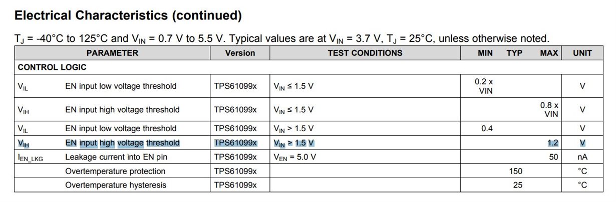
Input Voltage Thresholds (VIH / VIL)
Typical values:
- VIH: 0.6–0.7 × VDD
- VIL: 0.2–0.3 × VDD
Some parts use absolute thresholds (e.g., 1.2 V), not ratios.
Input Leakage Current
Usually:
- Tens of nanoamps (good ICs)
- Up to microamps (older or high-voltage parts)
Leakage matters in coin-cell designs.
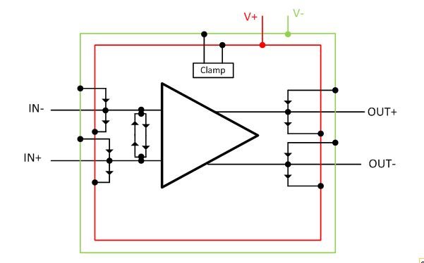
Absolute Maximum Ratings
Never exceed:
- Vpin > VDD + 0.3 V
- Vpin < GND − 0.3 V
Violating this invites latch-up.
Back-Powering Risks
Driving shutdown high while VDD = 0 can:
- Power the IC through ESD diodes
- Cause ghost operation
- Damage thin-oxide logic
Golden rule:
If VDD is off, the shutdown pin must not be driven beyond safe limits.
3. How Shutdown Pins Behave in Real Circuits
Active-High vs Active-Low
- Active-High: EN = 1 → ON
- Active-Low: SHDN = 0 → ON
Always confirm polarity in the datasheet. Never assume.
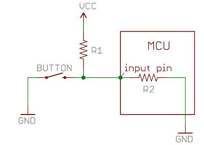
Internal Pull-Ups and Pull-Downs
Many ICs include weak internal resistors.
| Internal Pull | Typical Range | Default State |
|---|---|---|
| Pull-up | 100 kΩ – 1 MΩ | ON |
| Pull-down | 100 kΩ – 500 kΩ | OFF |
Overriding Internal Pulls
External resistors:
- Improve noise immunity
- Define power-up behavior
- Meet safety requirements
Use 10 kΩ–100 kΩ externally unless otherwise specified.
4. Timing, Glitches, and Power Sequencing
Shutdown pins are not instantaneous switches.
Turn-On Delay
Includes:
- Reference startup
- Soft-start ramp
- Output stabilization
Ranges from microseconds to milliseconds.
Turn-Off Behavior
Some ICs:
- Discharge outputs actively
- Leave outputs floating
This affects downstream rails.
Glitch Sensitivity
Fast edges or EMI can:
- Momentarily enable the IC
- Cause audible noise
- Trigger inrush current
RC filtering is cheap insurance.
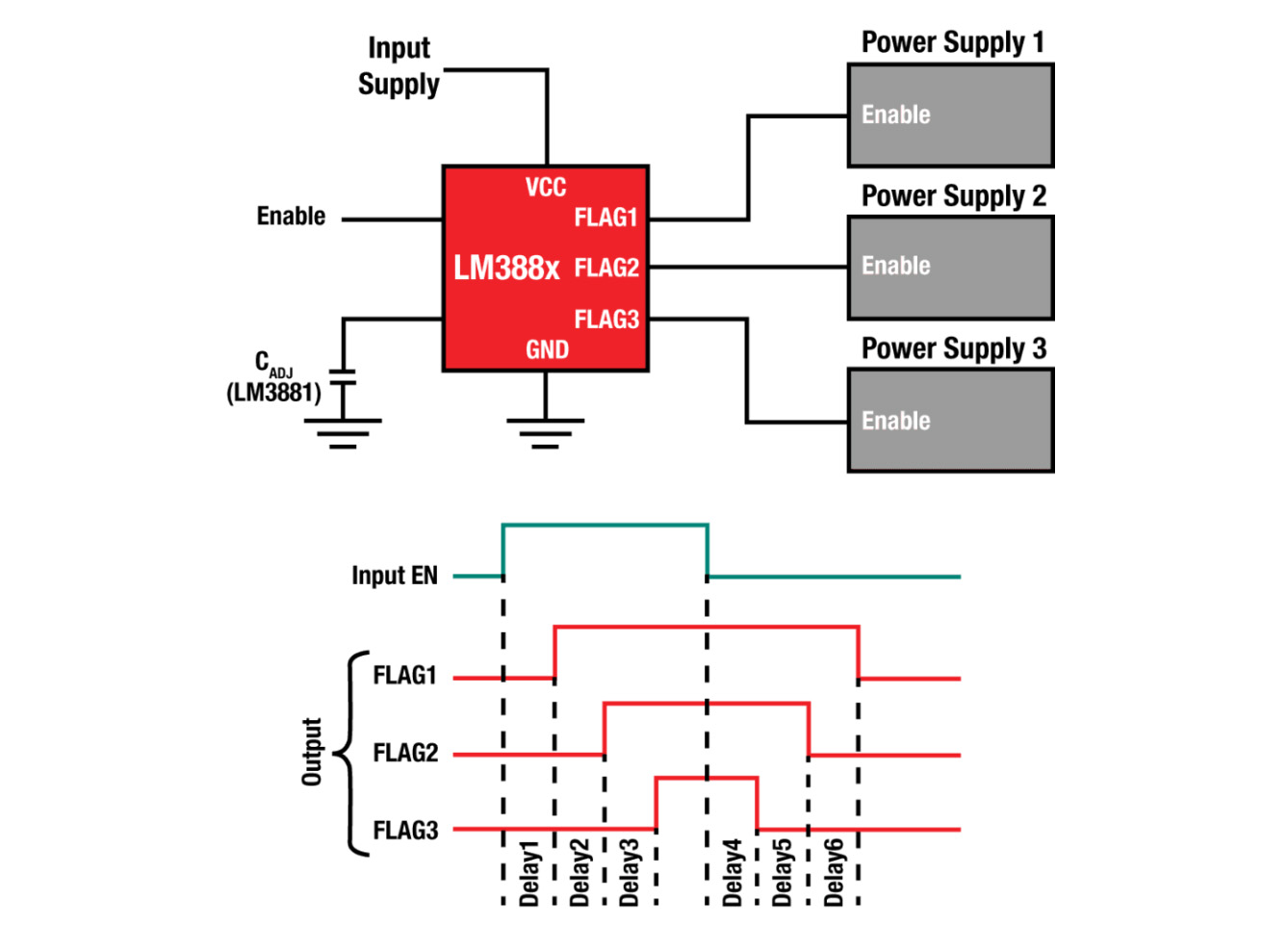
Multi-IC Sequencing
In systems with multiple rails:
- Core voltage first
- I/O rails next
- Analog last
Shutdown pins enforce this order cleanly.
5. MCU and Logic Interface Design
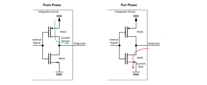
Push-Pull vs Open-Drain
- Push-pull: Simple, fast
- Open-drain: Safe when voltages differ
Logic-Level Compatibility
| MCU Level | Safe for Shutdown Pin? |
|---|---|
| 1.8 V | Sometimes |
| 3.3 V | Usually |
| 5 V | Only if rated |
Always check VIH max ratings.
Power-Up Race Conditions
If MCU boots slowly:
- IC may turn on unintentionally
- Outputs may glitch
Fixes:
- External pull-downs
- RC delay
- Supervisors
6. Shutdown Pins During Faults and Protection Events
Protection blocks often override shutdown logic.
Common Interactions
- UVLO: Forces shutdown regardless of pin
- OTP: May latch off until pin toggles
- OCP/OVP: Auto-restart or latch-off
Auto-Restart vs Latch-Off
| Behavior | Result |
|---|---|
| Auto-restart | Periodic retry |
| Latch-off | Requires pin toggle |
Know which you are buying.
7. Measuring Shutdown and Quiescent Current Correctly
Datasheet Numbers
- Typical: Marketing-friendly
- Maximum: Design-relevant
Always design to maximum.
Common Measurement Mistakes
- Forgetting pull-ups
- Measuring board leakage
- Leaving GPIOs floating
Use:
- Guard rings
- Clean flux
- Short traces
Nanoamps demand discipline.
8. Best Practices, Mistakes, and Design Checklists
Common Design Mistakes
- Leaving shutdown pins floating
- Driving pins before VDD is valid
- Using shutdown as a power switch
- Long, noisy enable traces
PCB and EMI Tips
- Route near ground
- Add RC filters (1–10 ms)
- Avoid parallel routing with switching nodes
Final Design Checklists
Shutdown Behavior Selection
- Default state defined?
- True power-off or partial?
- Recovery behavior clear?
Before Schematic Freeze
- VIH/VIL verified
- MCU compatibility checked
- External pulls sized
- Fault interactions reviewed
Final Thoughts
Shutdown pins are small.
Their impact is massive.
They decide:
- Battery life or failure
- Clean startup or chaos
- Compliance or redesign
Treat them as power-architecture tools, not simple logic pins.
Because in modern electronics, control is power.
