

Understanding Gain Bandwidth Product (GBW): What It Really Means for Op-Amp Design and Selection
In op-amp design, few specifications cause more confusion than Gain Bandwidth Product (GBW).
It looks simple. It sounds powerful. Yet it is often misused.
GBW is not a bonus feature.
It is a hard limit.
As the old engineering saying goes:
“You can’t get something for nothing.” — attributed to classical control theory texts
This article explains what GBW really means, why it matters, and how to use it correctly in real designs—without myths, shortcuts, or guesswork.
1. What Is Gain Bandwidth Product (GBW)?
Gain Bandwidth Product (GBW) is the product of an op-amp’s closed-loop gain and its usable bandwidth.
Core definition
[
\text{GBW} = \text{Gain} \times \text{Bandwidth}
]
If an op-amp has:
- GBW = 10 MHz
- Closed-loop gain = 10
Then the bandwidth is:
- 1 MHz
Why GBW is a trade-off
GBW describes a conservation law.
When gain goes up, bandwidth goes down. Always.
GBW does not mean:
- Faster response
- Better signal quality
- More accuracy by default
It only tells you how much frequency range remains after gain is applied.
The “constant GBW” assumption
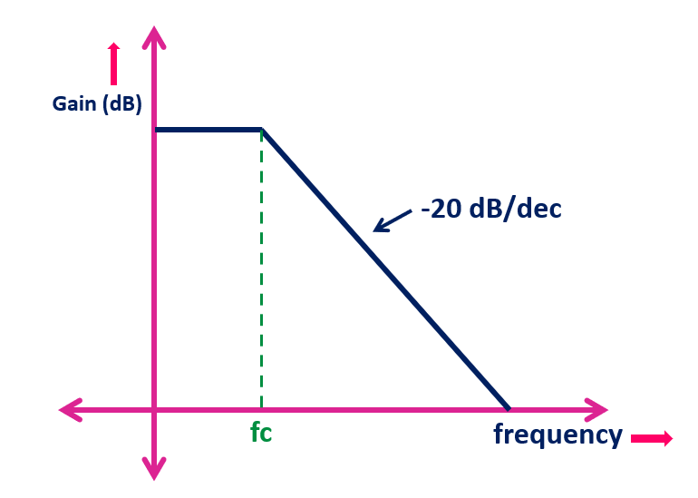
Most internally compensated voltage-feedback op-amps behave like this:
- One dominant pole
- −20 dB/decade roll-off
- Nearly constant GBW
This is an approximation, not a law of nature. Real devices bend the rule.
2. How to Visualize GBW in an Op-Amp


The best way to understand GBW is to see it.
Frequency response view
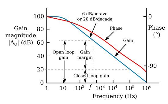
On a Bode plot:
- Open-loop gain starts very high
- Gain falls with frequency
- The point where gain hits 1× (0 dB) defines the unity-gain bandwidth
That frequency is the GBW.
Closed-loop behavior
When you set gain externally:
- The gain line moves down
- The bandwidth shrinks proportionally
Phase matters
Near the GBW limit:
- Phase shift increases
- Group delay rises
- Stability margin shrinks
Key takeaway:
GBW sets the edge where accuracy fades and instability begins.
3. Why GBW Matters in Real-World Applications
Ignoring GBW does not cause subtle problems.
It causes obvious failures.
Signal integrity and accuracy
Insufficient GBW leads to:
- Gain error
- Amplitude droop
- Frequency-dependent distortion
Timing and control loops
In feedback systems:
- Low GBW increases loop delay
- Phase margin collapses
- Oscillation becomes likely
Waveform fidelity
- Sine waves lose amplitude
- Square waves round off
- Fast edges disappear
Certification and reliability
Designs that “almost work” often:
- Fail EMI testing
- Drift over temperature
- Break under tolerance stacking
4. Practical Example: How GBW Limits Your Design
Let’s use a 10 MHz GBW op-amp.
Bandwidth at common gains
| Closed-Loop Gain | Bandwidth |
|---|---|
| 1× | 10 MHz |
| 10× | 1 MHz |
| 100× | 100 kHz |
What this means
If your signal is:
- 500 kHz
- Gain = 20×
You already exceed the GBW limit.
The result:
- Lower gain than expected
- Phase error
- Distortion
When degradation starts
Performance degrades well before the −3 dB point.
Good designs use only 10–20% of the theoretical limit.
5. GBW vs Slew Rate (SR): Two Different Speed Limits
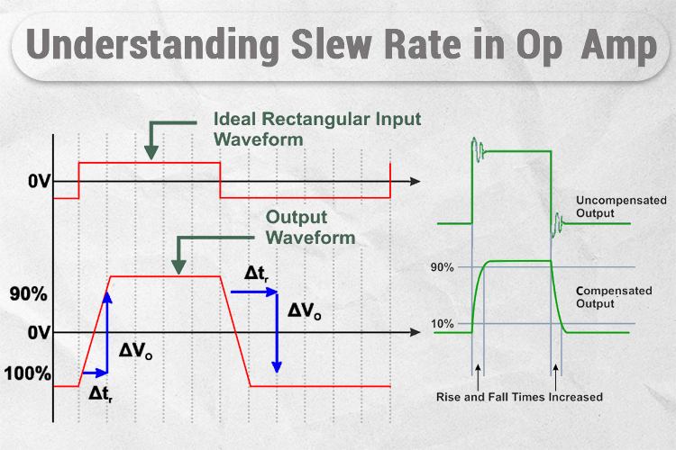


GBW and slew rate are often confused. They are not the same.
Small-signal vs large-signal
- GBW limits small-signal frequency response
- Slew Rate limits how fast voltage can change
When slew rate dominates
Even with enough GBW:
- Large amplitudes
- High frequencies
Can cause slew-rate distortion.
Rule of thumb
[
\text{Required SR} \ge 2\pi f V_{peak}
]
Common failure
Designers check GBW
…but forget slew rate.
The result: distorted waveforms that simulations never showed.
6. GBW in Non-Ideal and Real Op-Amps
Real op-amps are not single-pole systems.
Multi-pole behavior
Additional poles cause:
- Non-constant GBW
- Faster phase loss
- Reduced stability margin
Why datasheet plots matter
The headline GBW number hides:
- Peaking
- Gain compression
- Phase collapse
Always read:
- Open-loop gain vs frequency
- Phase margin vs load
- Closed-loop bandwidth curves
Stability implications
Higher GBW without proper compensation can:
- Ring
- Oscillate
- Radiate EMI
7. GBW, Stability, and Reliability Considerations
High GBW is powerful—but dangerous.
Phase margin and loop stability
As bandwidth increases:
- Phase margin shrinks
- Noise gain rises
- Layout becomes critical
Failure modes near GBW
- Output ringing
- Bursty oscillation
- Intermittent EMI failures
Long-term risks
Marginal designs:
- Fail temperature cycling
- Drift with aging
- Break during production variation
Too much GBW?
Excess GBW can:
- Increase noise
- Reduce EMI immunity
- Increase cost without benefit
8. GBW Design Rules of Thumb and Selection Strategy

Safe GBW ratios
| Application Type | Recommended GBW |
|---|---|
| General analog | ≥10× signal freq |
| Precision | ≥20× |
| Control loops | ≥30× |
Selection checklist
Before choosing an op-amp:
- Required gain?
- Signal frequency?
- Signal amplitude?
- Load capacitance?
- Temperature range?
Procurement risks
Second-source parts may:
- List same GBW
- Behave very differently
Always qualify behavior, not just numbers.
Summary: How to Use GBW Correctly and Confidently
GBW is not a speed rating.
It is not a quality score.
It is a boundary condition.
What GBW tells you
- Maximum usable bandwidth at a given gain
- Where accuracy begins to degrade
What GBW does not tell you
- Slew-rate performance
- Noise behavior
- Stability margin
- Large-signal fidelity
Final lesson
As electronics pioneer Bob Widlar famously implied through his designs:
Understanding limits is more important than chasing specifications.
Use GBW as a design constraint, not a marketing number.
That is how robust, stable, and reliable op-amp systems are built.
