

Understanding Drift Over Temperature
A practical, engineer-approved guide for design, selection, and decision-making
Introduction
Temperature drift is silent. Invisible. And often underestimated.
Yet it is one of the most common reasons electronic systems fail to meet specifications in the real world. A circuit that works perfectly at room temperature can slowly slide out of tolerance when heat rises—or accuracy collapses when cold creeps in.
This guide explains drift over temperature in clear language, without watering it down. Engineers will find depth. Product managers will find clarity. Buyers will find risk awareness.
As the old engineering proverb says:
“What you don’t measure over temperature, you will debug in the field.”
What Is Drift Over Temperature?
Drift over temperature is the change in an electrical parameter caused by temperature variation, even when all other conditions remain constant.
In simple terms:
The circuit changes because it gets hotter or colder.
Parameters commonly affected
- Voltage output
- Current bias
- Gain and offset
- Frequency and timing
- Sensor sensitivity and zero point
Plain-language explanation
Imagine a ruler that stretches slightly when warm and shrinks when cold. The markings stay the same—but your measurements drift. Electronics behave the same way.
Drift is not failure.
Drift is predictable change.
And predictable change must be managed.
Temperature Drift vs. Related Concepts
Drift is often confused with other specifications. Mixing them up leads to bad decisions.
| Concept | What It Means | Why It’s Different |
|---|---|---|
| Temperature coefficient (TCR) | Rate of change per °C | A slope, not total error |
| Accuracy | Closeness to true value | Accuracy can be good at one temperature |
| Precision | Repeatability | You can repeat the wrong value |
| Aging | Change over time | Happens even at constant temperature |
| Thermal hysteresis | Path-dependent error | Depends on heating vs. cooling |
Key insight:
A component can be accurate, precise, and still drift badly over temperature.
Why Temperature Drift Happens
Temperature drift is not a defect. It is physics.
1. Material property changes
- Resistance changes with heat
- Dielectric constants shift
- Mechanical expansion alters geometry
2. Semiconductor physics
- Carrier mobility decreases as temperature rises
- Threshold voltages shift
- Leakage currents increase exponentially
3. Packaging and stress
- Different materials expand at different rates
- Bond wires stretch
- PCB stress alters device behavior
As William Thomson (Lord Kelvin) famously said:
“If you cannot measure it, you cannot improve it.”
Temperature drift is measurable—and therefore manageable.
Short-Term vs. Long-Term Temperature Drift
Not all drift happens at the same pace.
Short-term drift
Occurs during temperature change
- Power-up warm-up effects
- Rapid ambient swings
- Transient self-heating
Long-term drift
Appears after stabilization
- Repeated thermal cycling
- Mechanical fatigue
- Gradual parameter migration
| Time Scale | Typical Cause | Design Impact |
|---|---|---|
| Seconds–minutes | Self-heating | Startup accuracy |
| Hours | Ambient changes | Operational stability |
| Years | Thermal cycling | Lifetime reliability |
Designs must survive both moments and years.
Common Parameters Affected by Drift
Different components drift in different ways.
Analog building blocks
- Voltage references: output voltage drift
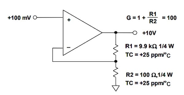
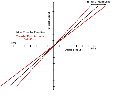
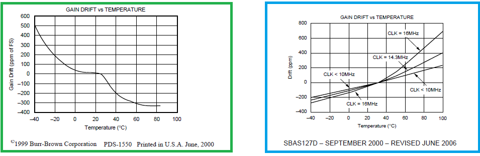
- Op-amps: offset voltage, bias current, gain
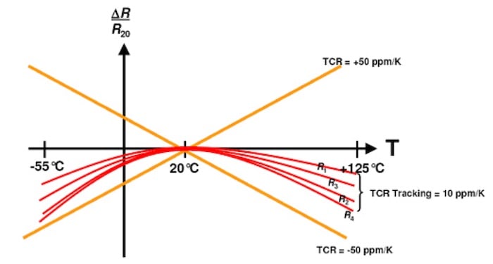
- Resistors: resistance change (ppm/°C)
Timing and frequency
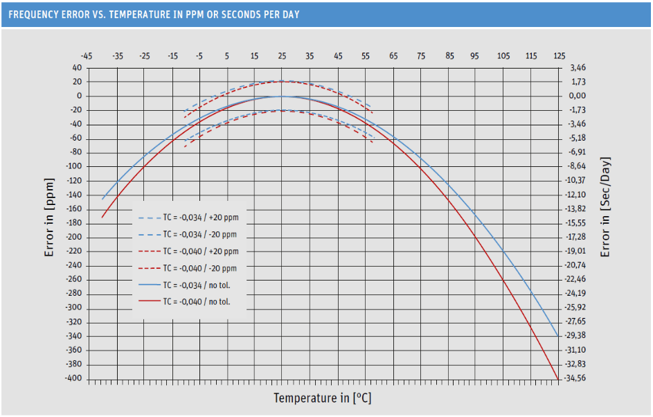
- Crystal oscillators: frequency drift
- RC clocks: severe temperature sensitivity
Sensors
- Offset drift
- Sensitivity drift
- Nonlinearity changes
| Component | Typical Drift Impact |
|---|---|
| Voltage reference | System-wide error |
| Op-amp | Amplified offset |
| Sensor | False readings |
| Clock | Timing and sync loss |
Drift in Different Component Categories

ADCs and DACs
- Reference drift dominates total error
- INL/DNL change subtly with temperature
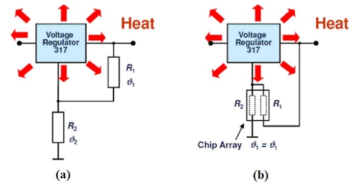
Voltage regulators and LDOs
- Output voltage shifts
- Dropout voltage changes
- Load regulation degrades
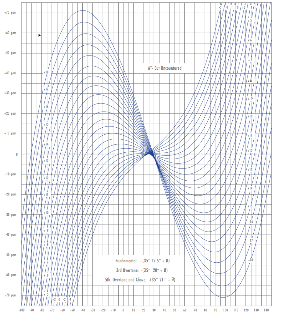
Oscillators and clocks
- Crystals show curved temperature behavior
- TCXOs reduce but do not eliminate drift
Sensors
- MEMS sensors are highly temperature-sensitive
- Environmental sensors require compensation
Rule of thumb:
If it measures, amplifies, or times something—it drifts.
Digital vs. Analog Drift Considerations
Why analog suffers more
Analog signals are continuous.
Temperature nudges them constantly.
Digital logic has thresholds.
Analog has slopes.
Limits of digital correction
- Calibration tables need memory
- Sensors still drift between points
- Temperature gradients break assumptions
Mixed-signal reality
- ADC drift + sensor drift = compounded error
- Digital correction cannot fix bad analog design
Digital helps—but it never replaces physics.
How Temperature Drift Is Measured and Specified

Measurement methods
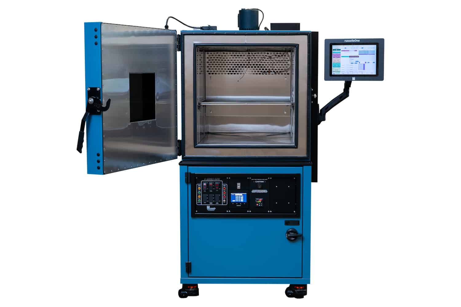
- Temperature sweep testing
- Soak testing (steady-state)
- Thermal ramp testing
Specification units
- ppm/°C
- µV/°C
- % over full range
Specification traps
- Typical vs. maximum
- Narrow test ranges
- Ideal lab conditions
Always ask:
Over what temperature range was this measured?
Why Drift Over Temperature Matters in Real Systems
Drift is not academic. It is expensive.
Technical consequences
- Measurement error
- Control loop instability
- System-level misalignment
Business consequences
- Failed compliance testing
- Field returns (RMAs)
- Redesign delays
- Reputation damage
| Impact Area | Cost of Ignoring Drift |
|---|---|
| Industrial control | Process instability |
| Automotive | Safety risk |
| Medical | Regulatory failure |
| Aerospace | Mission loss |
How Engineers Reduce and Manage Drift
Component selection
- Low-drift references
- Precision resistors
- Matched transistor pairs
Circuit techniques
- Ratiometric design
- Chopper-stabilized amplifiers
- Differential measurement
Thermal design
- Even heat distribution
- Controlled airflow
- Isolation of heat sources
Good thermal design is good electrical design.
Calibration and Software Compensation
Calibration is powerful—but limited.
Calibration approaches
- Factory calibration
- Field recalibration
- Continuous self-calibration
Software techniques
- Lookup tables
- Polynomial correction
- Temperature-aware algorithms
Warning:
Calibration compensates for known drift.
It cannot fix uncharacterized behavior.
System-Level Drift Management
Drift accumulates.
One component drifts.
Then another.
Then the enclosure adds gradients.
System considerations
- Board-level hot spots
- Sensor-to-ADC thermal mismatch
- Enclosure insulation effects
Error budgeting must include temperature at every level.
Conclusion
Temperature drift is not optional.
It is unavoidable.
But it is also understandable, predictable, and controllable.
Key takeaways
- Drift is different from accuracy
- Analog circuits feel temperature first
- Datasheets hide as much as they reveal
- System-level thinking is mandatory
The best designs do not fight temperature.
They design with it.
And that is the difference between products that work in the lab—and products that succeed in the field.
