
TPS5430 Buck Converter Module Design & Arduino / ESP32 Power Supply Projects
Introduction
Power is the silent backbone of every embedded system.
If power fails, everything fails.
The TPS5430 buck converter has earned its popularity because it solves a hard problem simply: converting wide input voltages into stable, efficient DC rails for microcontrollers like Arduino and ESP32.
From hobbyist prototypes to industrial control boards, TPS5430 sits in a sweet spot:
- Wide input range
- Solid 3A output capability
- Proven stability
- Minimal external parts
As the proverb often quoted in engineering goes:
“Good power design is invisible—until it isn’t.” — Texas Instruments power design notes
This article dives deep into design, modules, calculations, layout, efficiency, noise control, and real-world Arduino/ESP32 usage, with practical clarity, not datasheet theory overload.
Understanding the TPS5430 Buck Converter IC
The TPS5430 is a non-synchronous step-down (buck) regulator developed by Texas Instruments. It integrates a high-side MOSFET, switching at a fixed 500 kHz, allowing compact inductors and fast transient response.
Key Electrical Characteristics (That Actually Matter)
| Parameter | Value | Why It Matters |
|---|---|---|
| Input Voltage | 5.5V – 36V | Works with 12V, 24V, automotive rails |
| Output Current | Up to 3A | Handles ESP32 Wi-Fi bursts |
| Switching Frequency | 500 kHz | Smaller inductors, cleaner layout |
| Control Mode | Voltage-mode | Predictable behavior, easy debugging |
Why Integrated MOSFET Is a Big Deal
- Lower BOM cost
- Fewer layout mistakes
- Better EMI control
- Higher reliability
Short sentence.
Less parts. Less risk.
TPS5430 Datasheet Deep Dive (What Designers Often Miss)
Datasheets hide traps in footnotes. TPS5430 is no exception.
Absolute Max vs Recommended Conditions
Running near absolute maximum ratings reduces lifetime. Always design with margin:
- Use ≤30V max input in real systems
- Derate current by temperature
Enable (EN) Pin and UVLO
The EN pin allows:
- Controlled startup
- Power sequencing
- Brownout protection
Many cheap modules tie EN directly to VIN. That works—but it’s not optimal.
Internal Compensation: Why Stability Is Easy
Unlike many controllers, TPS5430 uses internal loop compensation.
This means:
- No compensation network to tune
- Predictable stability
- Fewer oscillation failures
Light-Load Behavior
TPS5430 stays in continuous conduction mode.
At very light loads, efficiency drops—but output stays clean.
For MCUs, stability beats peak efficiency.
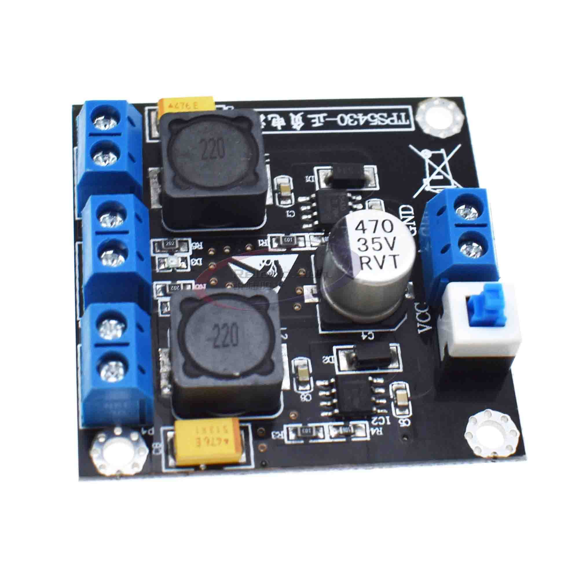
TPS5430 Module vs Custom Buck Converter Design
| Aspect | Module | Custom PCB |
|---|---|---|
| Design Time | Very low | High |
| Cost (Volume) | Higher | Lower |
| Layout Quality | Unknown | Fully controlled |
| Reliability | Varies by vendor | Engineer-defined |
When Modules Make Sense
- Prototypes
- Lab tools
- Low-volume products
When Custom Design Wins
- Industrial environments
- EMI-sensitive ESP32 designs
- High current or thermal constraints
Golden rule:
“Modules save time. Layout saves products.”
Calculating Output Voltage for TPS5430
TPS5430 uses a simple resistor divider on the FB pin.
Formula:
[
V_{OUT} = 1.221V \times \left(1 + \frac{R_{TOP}}{R_{BOTTOM}}\right)
]
Common Designs
| Output | Rtop | Rbottom |
|---|---|---|
| 5V | 3.01kΩ | 1kΩ |
| 3.3V | 1.69kΩ | 1kΩ |
Accuracy Matters
- Use 1% resistors minimum
- Poor tolerance = wrong voltage
- ESP32 brownouts often start here
Short sentence.
Voltage errors reset boards.
Core Power Supply Design Considerations

Inductor Selection
- 15–22 µH typical
- Saturation current ≥ 4A
- Low DCR improves efficiency
Capacitors
- Input: Low-ESR ceramic + bulk electrolytic
- Output: Ceramic close to IC
Diode Choice
- Fast Schottky
- Low forward voltage
- Rated above VIN
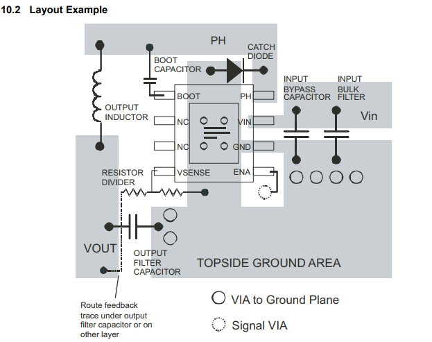
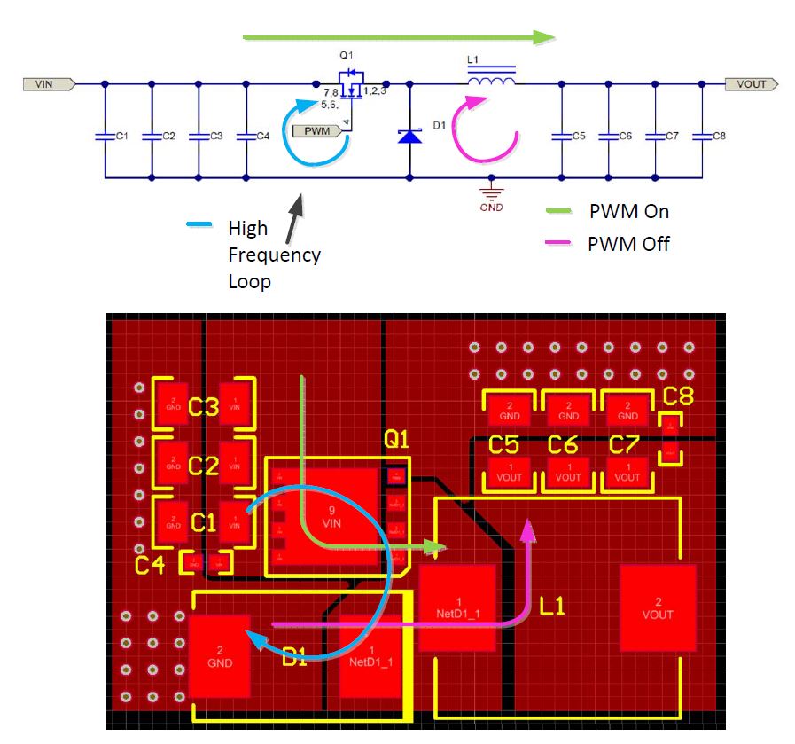
PCB Layout Rules (Non-Negotiable)
- Keep switch loop small
- Ground plane solid
- Feedback trace away from SW node
Bad layout beats good schematics—every time.
Noise, Ripple, and EMI Control (Critical for ESP32)

ESP32 is sensitive. Wi-Fi radios amplify power mistakes.
Ripple Control Techniques
- Proper output capacitor placement
- Optional LC post-filter for ADC rails
Grounding Strategy
- Single-point ground
- Separate power and signal return paths
EMI and Wi-Fi Stability
Poor buck design causes:
- Wi-Fi disconnects
- ADC noise
- Random resets
This is not theory.
This is field reality.
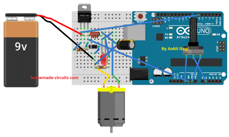
Using TPS5430 with Arduino and ESP32 Projects
Arduino Powering (7V–24V Inputs)
TPS5430 bypasses inefficient linear regulators.
- Less heat
- More current
- Stable 5V rail
ESP32 Powering (3.3V or 5V → LDO)
ESP32 can draw 700–900 mA peaks.
Handling Wi-Fi Current Bursts
- Add ≥470 µF bulk capacitor
- Keep power traces short
- Avoid breadboards
Most “ESP32 problems” are power problems.
Conclusion: Best Practices That Actually Work
TPS5430 remains a reliable, battle-tested buck converter for Arduino and ESP32 designs.
Use modules when speed matters.
Design your own PCB when reliability matters.
Key takeaways:
- Respect layout rules
- Design for transient current, not averages
- Filter noise before it reaches the MCU
- Use the EN pin wisely
In power design, simplicity is strength—but discipline is everything.
