
Junction Temperature vs Ambient Temperature: What You Must Know in Electronic Design
Thermal design is not optional.
It is decisive.
Many electronic failures trace back to one root cause: misunderstanding temperature. Designers look at ambient temperature (Ta). Failures happen because the silicon junction temperature (Tj) was ignored.
This article explains the difference clearly, practically, and deeply—without math overload.
Grade-7 reading level. Expert insight.
Understanding Ambient Temperature (Ta) in Electronic Systems
Ambient temperature is the temperature of the air surrounding the electronic system.
It sounds simple. It isn’t.
Ta is usually measured outside the IC, near the board or enclosure air. It does not account for self-heating.
Typical Ambient Temperature Ranges
| Application | Ambient Range |
|---|---|
| Consumer electronics | 0 °C to 40 °C |
| Industrial systems | −40 °C to 85 °C |
| Automotive electronics | −40 °C to 125 °C |
| Outdoor / harsh environments | −55 °C to 125 °C |
Why Ambient Temperature Alone Is Misleading
Ambient temperature ignores:
- Power dissipation inside the IC
- Heat from neighboring components
- Enclosure heat buildup
- Poor airflow
“You cannot manage what you do not measure.” — Peter Drucker
Ambient temperature is context, not truth.
The truth lives inside the silicon.

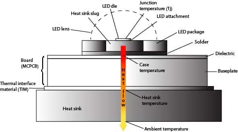
Understanding Junction Temperature (Tj) Inside ICs
Junction temperature is the temperature at the active silicon region where current flows.
This is where:
- Transistors switch
- Power is dissipated
- Failures begin
Why Junction Temperature Controls Reliability
Every major failure mechanism accelerates with higher Tj:
- Electromigration
- Dielectric breakdown
- Silicon aging
A rule of thumb used across the industry:
Every 10 °C rise in junction temperature cuts component life roughly in half.
Absolute Max vs Recommended Operating Tj
| Parameter | Typical Value |
|---|---|
| Absolute maximum Tj | 150 °C–175 °C |
| Recommended operating Tj | ≤125 °C |
| Reliability-focused target | ≤105 °C |
Operating near maximum Tj is legal.
It is not smart.
Junction Temperature vs Ambient Temperature: Core Differences
Ambient temperature is external.
Junction temperature is internal.
The gap between them depends on power dissipation and thermal resistance.
Power Changes Everything
If an IC dissipates power, junction temperature rises—even if ambient stays constant.
| Condition | Ambient (Ta) | Power | Junction (Tj) |
|---|---|---|---|
| Idle | 25 °C | Low | 30 °C |
| Active | 25 °C | High | 110 °C |
| Same Ta, higher power | 25 °C | Very high | 140 °C |
Failures follow Tj, not Ta.
Thermal Resistance: The Missing Link Designers Ignore
Thermal resistance tells you how hard it is for heat to escape.
The most used equation:
Tj = Ta + (P × θJA)
Where:
- P = power dissipated (W)
- θJA = junction-to-ambient thermal resistance (°C/W)
Key Thermal Resistance Parameters
| Parameter | Meaning |
|---|---|
| θJA | Junction → Ambient |
| θJC | Junction → Case |
| θJB | Junction → Board |
| θBA | Board → Ambient |
Why θJA Is Often Wrong
θJA is measured under JEDEC test boards:
- Fixed copper area
- Still air
- Ideal conditions
Real PCBs are messier.
Real temperatures are higher.
Datasheet thermal numbers are starting points, not guarantees.
How to Calculate Junction Temperature Accurately
Accuracy comes from realism.
Inputs You Must Get Right
- Worst-case power dissipation
- Real ambient temperature
- Real PCB thermal path
- Airflow conditions
Practical Example
Assume:
- Ta = 50 °C
- Power = 1.2 W
- θJA = 45 °C/W
Tj = 50 + (1.2 × 45) = 104 °C
Looks safe?
Only if θJA is accurate. Often, it isn’t.
Worst-Case vs Typical Design
| Approach | Risk |
|---|---|
| Typical values | High |
| Worst-case assumptions | Low |
| With margin (10–20 °C) | Best |
Design for stress, not comfort.
Measuring Junction Temperature in Real Hardware
You cannot touch the junction.
But you can estimate it.
Common Techniques
| Method | Accuracy | Notes |
|---|---|---|
| On-chip temperature sensor | High | Best option |
| Diode forward voltage | Medium | Needs calibration |
| Case temperature + θJC | Medium | Easy, indirect |
| IR camera | Low–Medium | Surface only |
Common Pitfalls
- Measuring case temperature and calling it Tj
- Ignoring thermal lag
- Measuring too early (no heat soak)
Heat needs time to settle.
So does truth.


Junction Temperature and Reliability Physics
Temperature accelerates failure.
The Arrhenius equation shows how reaction rates increase exponentially with temperature.
Failure Mechanisms Driven by High Tj
- Electromigration: metal atoms drift
- Dielectric breakdown: insulation weakens
- Solder fatigue: expansion mismatch
MTBF vs Junction Temperature
| Junction Temperature | Relative Lifetime |
|---|---|
| 85 °C | 1× |
| 105 °C | ~0.5× |
| 125 °C | ~0.25× |
Lower Tj equals longer life. Always.
Best Practices to Control Junction Temperature
Thermal control is a system problem.
What Actually Works
- Choose low-θ packages
- Increase PCB copper area
- Add thermal vias under the pad
- Improve airflow
- Use heatsinks when needed
Design Philosophy That Lasts
“Design for reliability, not just compliance.”
Meeting absolute maximum ratings is survival.
Designing below them is success.
Key Takeaways: Designing with Junction Temperature in Mind
- Ambient temperature is not enough
- Junction temperature decides failure or success
- Power dissipation is the hidden enemy
- Datasheet numbers are optimistic
- Thermal margin equals reliability margin
If you remember one thing:
👉 Design to junction temperature, not ambient temperature.
That single mindset shift separates fragile products from trusted ones.
