

AT24C04 Arduino Code: Complete Guide to EEPROM Programming, Addressing, and Reliable Use
Introduction
When developers search for “AT24C04 Arduino code”, they are rarely looking for a single sketch. They want clarity. They want confidence. And most of all, they want working, reliable EEPROM storage that does not fail in the field.
The AT24C04 is a small I²C EEPROM, yet it sits at the heart of many serious products—from calibration memory in sensors to configuration storage in industrial controllers. This guide goes beyond demos. It explains how the chip works, how Arduino code must handle it, and how to avoid silent data corruption.
As the old engineering proverb says:
“Memory is cheap. Debugging corrupted memory is not.”
This article focuses on real-world usage, production safety, and long-term reliability.
What Is the AT24C04 EEPROM?
Definition and Core Function
The AT24C04 is a 4-kilobit (512-byte) non-volatile EEPROM that communicates over the I²C bus. Unlike RAM, it retains data without power, making it ideal for persistent storage.
How Non-Volatile EEPROM Memory Works
EEPROM cells store charge in floating gates. Writes are slower than reads. Endurance is finite. These facts shape how Arduino code must behave.
Why AT24C04 Is Still Widely Used Today
Despite flash and FRAM alternatives, AT24C04 remains popular because it is:
- Cheap and widely available
- Simple to interface
- Supported by nearly every microcontroller
In embedded systems, boring reliability beats shiny novelty.
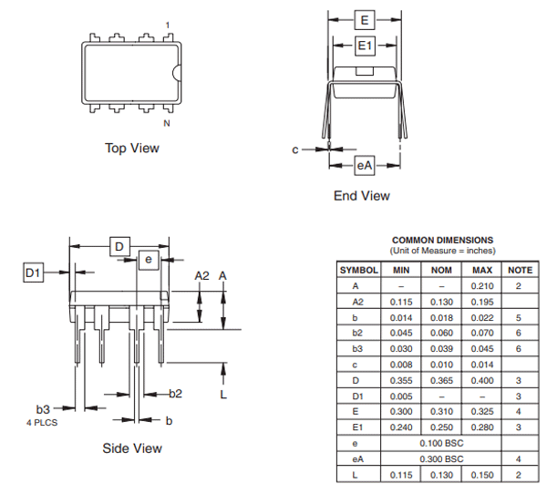
Key Technical Specifications of AT24C04
| Parameter | Value |
|---|---|
| Total Capacity | 512 bytes |
| Page Size | 16 bytes |
| Interface | I²C |
| Endurance | ≥ 1,000,000 writes |
| Data Retention | ≥ 100 years |
| Voltage Range | 1.7V – 5.5V |
Page Structure Matters
Writes are limited to 16-byte pages. Crossing a page boundary silently wraps data—one of the most common causes of corruption.
Address Pins and WP
Pins A0–A2 modify the I²C address. WP (Write Protect) can lock memory at the hardware level.
AT24C04 vs Other AT24Cxx EEPROMs
| Device | Capacity | Page Size | Code Changes Needed |
|---|---|---|---|
| AT24C02 | 256 bytes | 8 bytes | Yes |
| AT24C04 | 512 bytes | 16 bytes | Baseline |
| AT24C08 | 1 KB | 16 bytes | Yes |
Code Compatibility Reality
Most Arduino libraries compile across AT24Cxx chips—but that does not mean they behave correctly. Addressing rules change. Page boundaries change. Data loss follows careless assumptions.
Never reuse EEPROM code blindly.
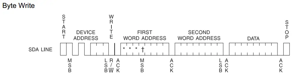
Understanding AT24C04 Addressing in Arduino Code
I²C Address vs Memory Address
Developers often confuse:
- Device address (0x50–0x57)
- Internal memory address (0–511)
These are separate concepts.
Block-Select Bits Explained
The AT24C04 internally divides memory into blocks. Some address bits are embedded in the I²C address itself. This is why naïve code fails above 256 bytes.
Common Addressing Mistakes
- Forgetting A0–A2 pins affect I²C address
- Writing beyond 0xFF without adjusting block bits
- Assuming linear addressing like larger EEPROMs
Addressing errors do not throw exceptions. They quietly corrupt data.
Interfacing AT24C04 with Arduino Hardware
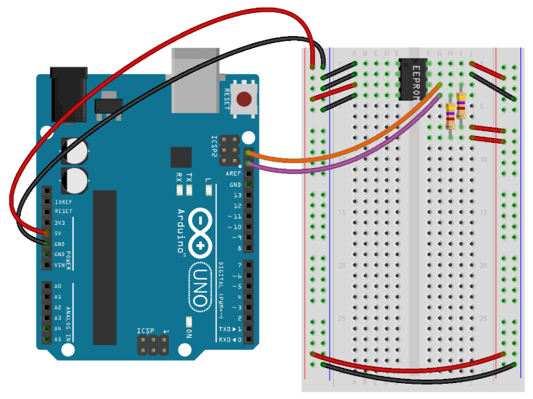
Wiring Essentials
- SDA → SDA, SCL → SCL
- 4.7kΩ pull-ups required (often already on Arduino boards)
- WP tied to GND for writes
Timing Constraints
EEPROM writes take up to 5 ms. Ignoring this delay causes failed writes that appear successful.
Patience is not optional in EEPROM code.
AT24C04 Arduino Code Fundamentals
Minimal Working Example
#include <Wire.h>

#define EEPROM_ADDR 0x50

void eepromWriteByte(uint16_t addr, byte data) {
  Wire.beginTransmission(EEPROM_ADDR | ((addr >> 8) & 0x01));
  Wire.write((byte)addr);
  Wire.write(data);
  Wire.endTransmission();
  delay(5);
}

byte eepromReadByte(uint16_t addr) {
  Wire.beginTransmission(EEPROM_ADDR | ((addr >> 8) & 0x01));
  Wire.write((byte)addr);
  Wire.endTransmission();

  Wire.requestFrom(EEPROM_ADDR | ((addr >> 8) & 0x01), 1);
  return Wire.read();
}
Byte vs Page Writes
- Byte writes are safe but slow
- Page writes are faster but dangerous without boundary checks
In production firmware, safety beats speed.
Page Write Risks and Data Corruption
What Happens When You Cross a Page Boundary
The EEPROM wraps around to the start of the page. No warning. No error.
Safe Page-Write Pattern
- Align writes to page start
- Split data across pages
- Never assume continuous memory
As Bruce Schneier famously said:
“Complexity is the enemy of security—and reliability.”
Data Integrity, Power Loss, and Write Protection

Power Failure Reality
If power drops mid-write, data may be partially written or corrupted.
Proven Safety Techniques
- Commit flags
- Version numbers
- Double-buffer storage
These patterns turn fragile EEPROM writes into robust storage systems.
WP Pin Best Practice
Use hardware write protection in shipped products. Software locks can fail. Hardware rarely does.
Testing, Reliability, and Production Readiness
Prototype vs Production Code
Prototype code assumes success.
Production code verifies everything.
Reliability Checklist
- ACK checked on every transaction
- Read-back verification enabled
- Writes minimized to extend endurance
- Address boundaries enforced
In embedded systems, what you don’t test will fail in the field.
Summary and Best Practices
- Understand addressing before coding
- Respect page boundaries
- Add write delays and verification
- Use WP pin for shipped devices
- Treat EEPROM as persistent storage, not RAM
The AT24C04 is small, simple, and powerful—but only when used correctly. With disciplined Arduino code and solid hardware design, it becomes a trustworthy foundation for long-term data storage.
If reliability matters, this chip—and this approach—will not disappoint.
