

How to Understand Package Thermal Resistance (θJA, θJC, θJB): A Practical Guide for Decision Makers & Engineers
Thermal resistance numbers look simple. One value. One unit. One line in a datasheet.
But behind θJA, θJC, and θJB lies a complex story of assumptions, test boards, airflow, and heat paths.
Misunderstand them, and products overheat, fail early, or require expensive redesigns.
Understand them well, and you gain confidence, margin, and cost control.
This guide explains what thermal resistance really means, when each metric applies, and how decision makers and engineers should use them in practice—without jargon overload.
1. What Is Package Thermal Resistance?
Thermal resistance describes how hard it is for heat to escape.
Think of heat like water flowing downhill. Thermal resistance is the narrow pipe slowing that flow. The higher the resistance, the hotter the chip gets for the same power.
The core idea
[
T_j = T_{ref} + (P \times \theta)
]
- Tj: junction temperature (inside the silicon)
- Pref: reference temperature (ambient, case, or board)
- P: power dissipation
- θ: thermal resistance (°C/W)
“You can’t measure junction temperature directly. You estimate it—and assumptions decide whether that estimate is safe or dangerous.”
Why it matters:
Junction temperature drives performance, reliability, and lifetime. Every 10°C increase roughly halves semiconductor life. That’s not theory. That’s field data.
2. Steady-State vs. Transient Thermal Conditions
Thermal resistance values are steady-state numbers. They assume the system has fully heated and stabilized.
Real products rarely behave that way.
When θ values work
- Constant power
- Long operating time
- Stable airflow
- No rapid load changes
When they break down
- Power bursts
- Startup surges
- Sleep–wake cycles
- Pulsed RF or motor drivers
In these cases, transient thermal impedance (Zθ) matters more than θJA.
Key insight:
θJA may say you’re overheating—while Zθ shows you’re perfectly safe for short bursts.
Ignoring this distinction leads to overcooling, bigger heat sinks, and unnecessary fans.
3. θJA — Junction-to-Ambient Thermal Resistance
θJA is the most quoted—and most abused—thermal number.
What θJA actually measures
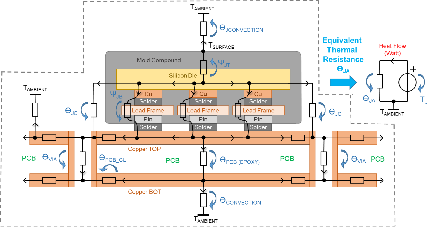
It represents heat flow:
- From the junction
- Through the package
- Through the PCB
- Into the surrounding air
All under specific test conditions.
Why θJA is not a constant
JEDEC defines:
- Board size and copper coverage
- Layer count (often 1s or 2s)
- Still air or light airflow
- Vertical orientation
Change any of these, and θJA changes—sometimes by 2× or more.
When θJA is useful
- Early feasibility checks
- Comparing package options from the same vendor
- Quick “order-of-magnitude” estimates
When θJA misleads
- Compact enclosures
- Heavy copper PCBs
- Forced airflow
- Chassis-coupled designs
Rule of thumb:
θJA is a screening tool, not a design guarantee.
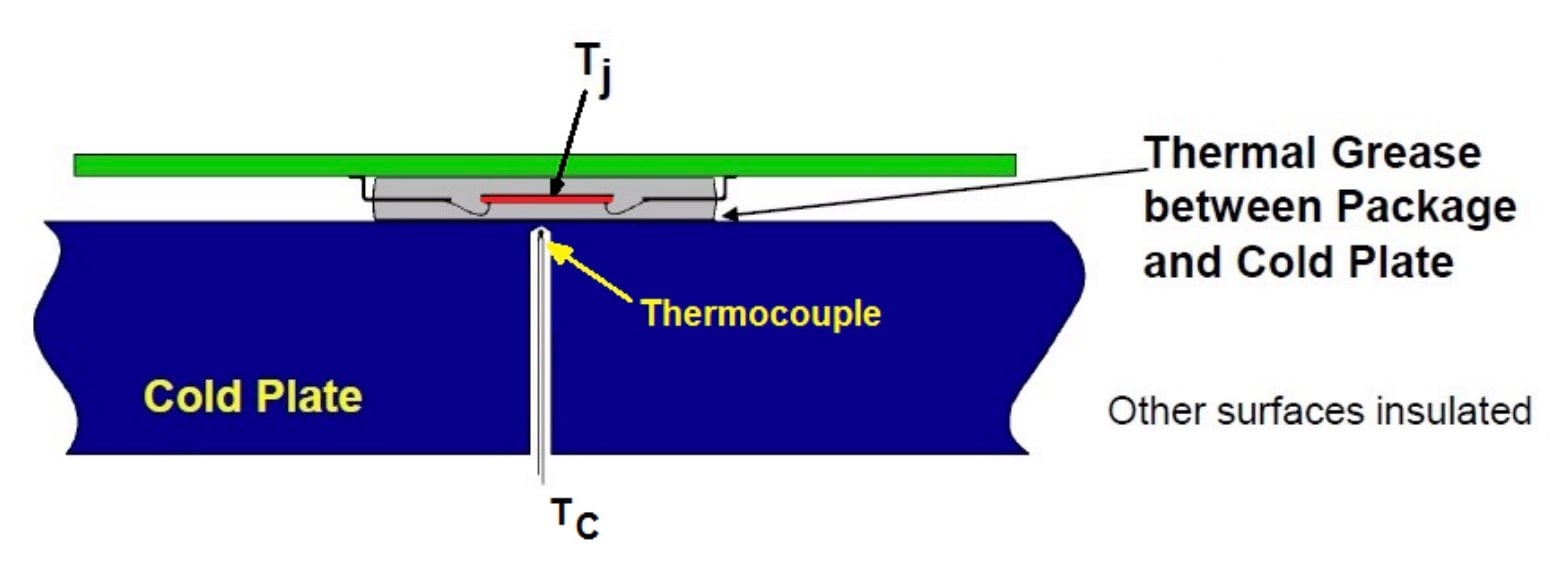
4. θJC — Junction-to-Case Thermal Resistance
θJC isolates what happens inside the package.
What θJC tells you
How efficiently heat moves:
- From the silicon die
- To the top or bottom package surface
It excludes the PCB and ambient air.
When θJC matters most
- Heat sinks
- Cold plates
- Metal chassis cooling
- High-power regulators and processors
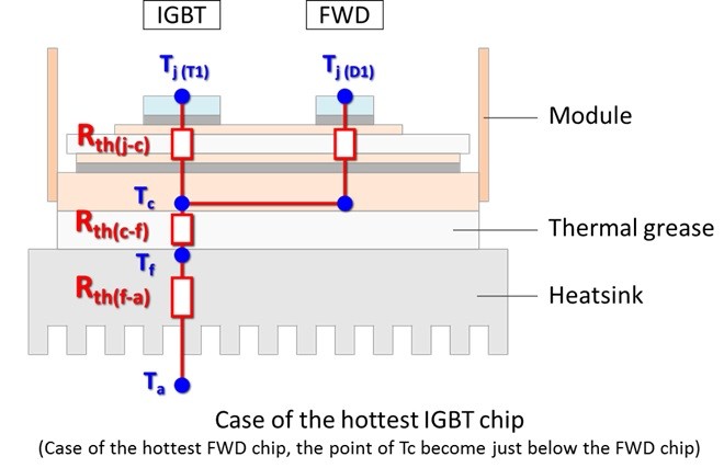
The missing piece: TIMs
θJC assumes perfect contact. Real systems need:
- Thermal grease
- Pads
- Phase-change materials
These add θCS (case-to-sink) resistance.
A great heat sink is useless if the interface is poor.
Common mistake:
Spending money on a premium heat sink while ignoring TIM thickness, pressure, or coverage.
5. θJB — Junction-to-Board Thermal Resistance
θJB is the quiet hero of modern electronics.
What θJB measures
Heat flow:
- From the junction
- Through the package
- Into the PCB
Measured at a defined board reference point.
Why θJB is critical today
- Fanless systems
- Wearables
- IoT devices
- Automotive modules
In these designs, the PCB is the heat sink.
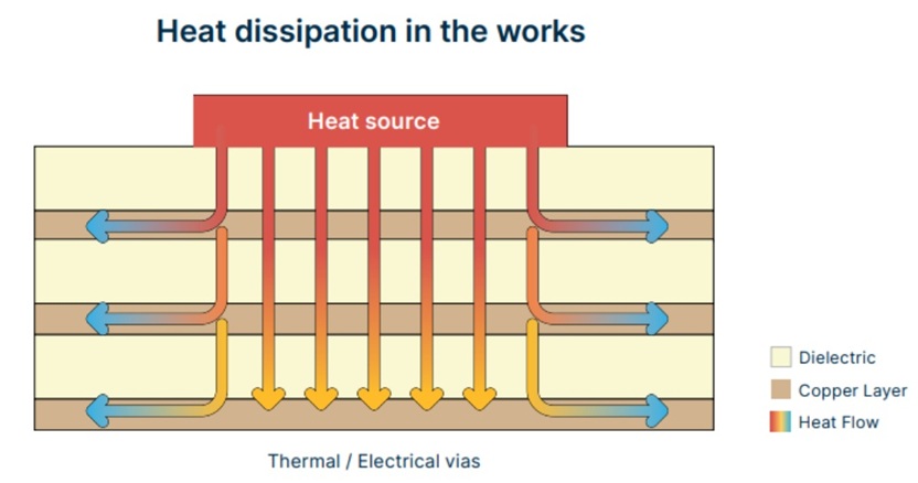
PCB factors that dominate θJB
- Copper plane area
- Internal ground layers
- Via density under exposed pads
- Board thickness
Small layout changes can reduce junction temperature by 10–20°C—without changing the IC.
6. JEDEC Standards and Why Datasheets Differ
Thermal numbers are not lies.
They’re contextual truths.
Why vendor numbers vary
Different vendors may use:
- 1-layer vs. 4-layer boards
- Different copper weights
- Different airflow assumptions
All are JEDEC-compliant.
What JEDEC ensures
- Repeatability
- Comparability within the same test method
- A baseline—not a prediction
Takeaway:
Never compare θJA numbers across vendors unless test conditions match.
7. PCB-Level Thermal Design That Actually Works
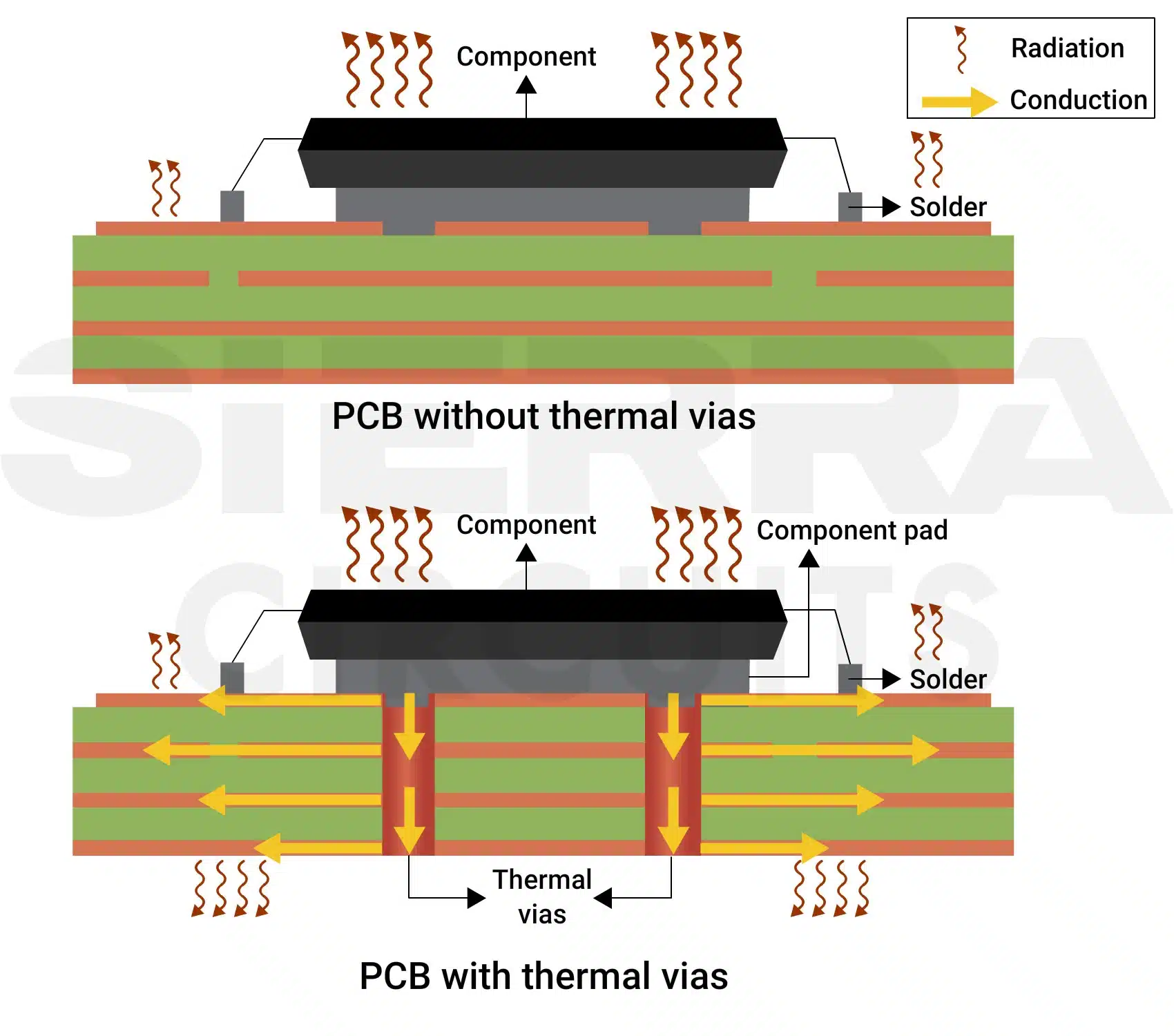

Most thermal problems are solved in copper—not with fans.
What works
- Large, continuous planes
- Multiple thermal vias under exposed pads
- Direct connections to internal ground planes
What doesn’t
- Isolated copper islands
- Thin traces as heat paths
- Over-reliance on solder mask openings
Cost vs. performance
| Stack-up | Cost Impact | Thermal Benefit |
|---|---|---|
| 2-layer | Low | Limited |
| 4-layer | Moderate | Excellent |
| 6-layer | High | Marginal gains |
Smart engineers optimize layout before hardware.
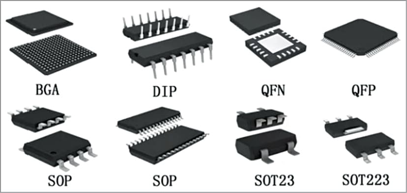
8. Package Type and Thermal Performance

Package choice sets the thermal ceiling.
General comparison
| Package | Thermal Path | Typical Use |
|---|---|---|
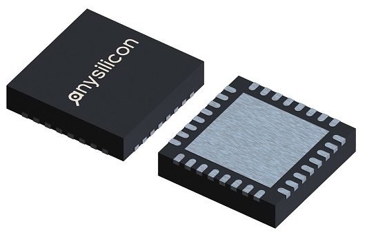
| QFN / DFN | Strong PCB coupling | Power ICs |
| BGA | Multi-path | Processors |
| SOP | Leads only | Low power |
| DIP | Poor | Legacy |
Exposed pads change everything
They:
- Slash θJB
- Improve consistency
- Demand good via design
Plastic vs. ceramic
- Plastic: cheaper, adequate
- Ceramic: better conductivity, higher cost
Choose based on power density, not tradition.
Key Takeaways
- θJA, θJC, and θJB answer different questions
- θJA is a screening metric—not reality
- θJC enables heat-sink-based cooling
- θJB unlocks PCB-driven thermal success
- Layout beats hardware in most designs
- Assumptions matter more than formulas
“Thermal resistance is not wrong. Misuse is.”
Understand the context. Respect the limits.
And thermal design becomes a decision tool—not a risk.
