

What Is Gate Charge in Power MOSFETs vs. Regulators?
Gate charge is one of those electrical terms that looks simple on paper but hides deep design consequences. Ignore it, and efficiency drops. Misjudge it, and EMI rises. Understand it, and your power design becomes faster, cooler, and more reliable.
This article explains what gate charge really is, how it behaves in discrete power MOSFETs, and why its role changes when MOSFETs are embedded inside voltage regulators. The goal is clarity. Plain language. Real engineering insight.
Understanding Gate Charge (Qg): Core Concepts
Gate charge (Qg) describes the total amount of electric charge required to move a MOSFET gate from OFF to fully ON. It is not just a static number. It represents energy, time, and loss.
Unlike resistance or voltage, gate charge directly links the control side of a MOSFET to its switching behavior.
Gate Charge vs. Gate Capacitance
Capacitance tells you how much charge is stored per volt.
Gate charge tells you how much charge must move in total.
Capacitance changes with voltage. Gate charge already includes that change. This is why engineers trust Qg more than capacitance values alone.
Why Gate Charge Exists in MOS-Based Devices
A MOSFET gate is insulated by an oxide layer. Electrically, it behaves like a capacitor network:
- Gate-to-source (Cgs)
- Gate-to-drain (Cgd)
- Gate-to-bulk
Every time the device switches, these capacitances must be charged and discharged. That motion of charge is gate charge.
Why Gate Charge Matters
Gate charge directly affects:
- Switching speed
- Gate drive power loss
- EMI and ringing
- Thermal stress
- Long-term reliability
In high-frequency designs, Qg can matter more than RDS(on).
Mathematical and Quantitative View of Gate Charge
Gate charge connects electrical theory with real loss mechanisms.
Relationship Between Qg, Vgs, and Capacitance
In simplified form:
Qg ≈ ∫ C(V) dV
Because capacitance varies with voltage, this integral matters. Qg captures that complexity in a single number.
Key Formula Engineers Use
| Parameter | Formula | Meaning |
|---|---|---|
| Gate drive loss | Qg × Vgs × fsw | Power lost driving the gate |
| Average gate current | Qg × fsw | Driver load |
| Switching speed | Ig / Qg | Faster driver, faster switching |
Every switching event consumes energy. Multiply it by frequency, and it becomes heat.
Why Qg Is More Practical Than Capacitance
Capacitance values assume linear behavior. MOSFETs are not linear during switching. Gate charge reflects real switching conditions. That is why datasheets highlight Qg curves instead of only capacitance tables.
How Gate Charge Works in Power MOSFETs
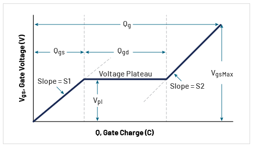
The gate does not charge in one smooth motion. It happens in stages.
The Gate Charging Process
- Cgs Charging Phase
The gate voltage rises to threshold. The channel forms. - Miller Plateau (Cgd)
The gate voltage stalls. Drain voltage changes instead.
This phase dominates switching loss. - Final Gate Rise
The MOSFET reaches full enhancement.
This sequence explains why Qg is split into subcomponents.
Key Datasheet Parameters
| Symbol | Description |
|---|---|
| Qg | Total gate charge |
| Qgs | Gate-to-source charge |
| Qgd | Gate-to-drain (Miller) charge |
Qgd is the most critical. It defines how fast voltage transitions occur.
Impact of Gate Drive Voltage
A MOSFET driven at 10 V has higher Qg than the same device driven at 5 V.
Logic-level MOSFETs reduce required voltage, but not always total charge. Always read the Qg vs. Vgs curve, not just the headline number.
Practical Design Trade-Offs in Discrete Power MOSFETs
No MOSFET is perfect. Every choice is a trade.
High Qg vs. Low Qg
- Low Qg → Faster switching, lower drive loss, more EMI risk
- High Qg → Slower switching, higher drive loss, cleaner waveforms
Fast is not always better.
Dynamic vs. Static Loss
| Loss Type | Dominant Parameter |
|---|---|
| Conduction loss | RDS(on) |
| Switching loss | Qg, Qgd |
| Gate drive loss | Qg × fsw |
At high frequency, switching loss can exceed conduction loss.
Temperature and Process Effects
- Gate charge slightly increases with temperature
- Trench MOSFETs offer low RDS(on) but higher Qg
- Planar devices switch cleaner but waste conduction power
Reliability improves when gate oxide stress is minimized. Excessive gate drive hurts lifetime.
Gate Charge and Gate Driver Interaction
A MOSFET never works alone. The gate driver is half the system.
Peak Gate Current Requirements
Fast switching requires high peak current. If the driver is weak, the MOSFET lingers in the linear region. Heat rises.
Matching Qg to Driver Strength
| Driver Capability | Suitable MOSFET |
|---|---|
| < 500 mA | Low-Qg MOSFET |
| 1–2 A | Medium-Qg MOSFET |
| > 5 A | Large power MOSFET |
Mismatch causes inefficiency and EMI.
Risks of Under-Driving High-Qg Devices
- Slow turn-off
- Shoot-through
- Ringing
- Excess heat
Gate charge sets the minimum driver requirement.
Gate Charge in Voltage Regulators
In switching regulators, MOSFETs are already inside the IC.
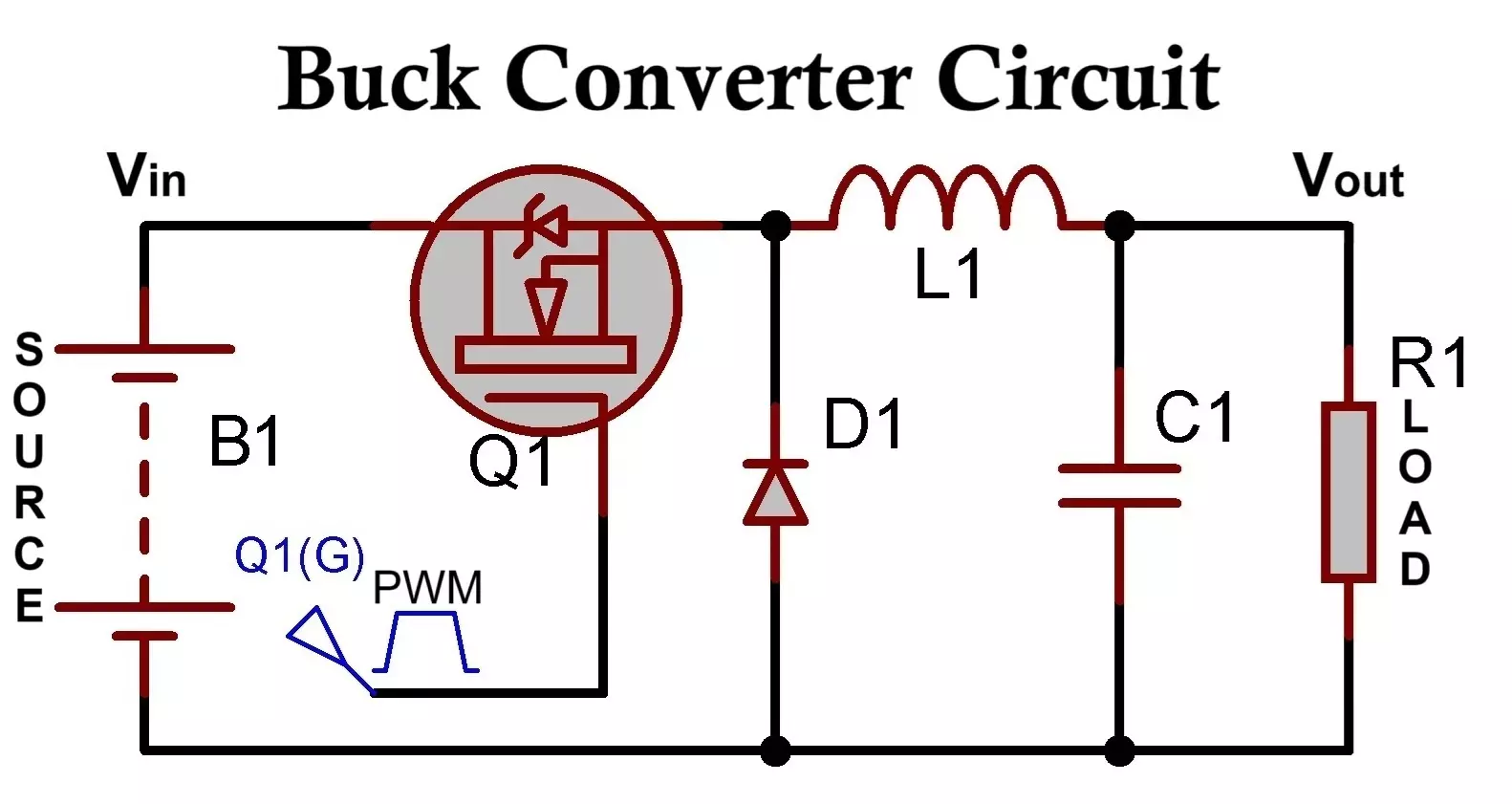
Internal MOSFETs in Switching Regulators
Buck, boost, and buck-boost regulators use integrated MOSFETs optimized for:
- Fixed frequency
- Known load range
- Known thermal limits
You rarely see Qg listed directly.
How Gate Charge Affects Regulator Efficiency
Gate charge loss is included in the efficiency curve. At light load, gate drive loss dominates. At heavy load, conduction loss takes over.
Why Gate Charge Is Less Critical in LDOs
Linear regulators do not switch. Their internal MOSFETs stay in the linear region. Gate charge exists, but it does not cycle. No switching. No repetitive gate loss.
Synchronous vs. Non-Synchronous Regulators
Synchronous designs use two MOSFETs instead of one.
Gate Charge Role in Synchronous Bucks
Both high-side and low-side MOSFETs switch every cycle. Total gate charge doubles. Driver timing becomes critical.
Dead-Time and Shoot-Through
Too much gate charge slows transitions. Too little dead-time causes cross-conduction. Vendors carefully tune Qg internally to balance efficiency and safety.
Power MOSFETs vs. Regulators: Key Differences
| Aspect | Discrete MOSFET | Integrated Regulator |
|---|---|---|
| Gate drive | External | Internal |
| Qg visibility | Explicit | Abstracted |
| Design freedom | High | Limited |
| Optimization | User responsibility | Vendor optimized |
With discrete MOSFETs, Qg is your problem.
With regulators, Qg is already priced in.
When Gate Charge Truly Matters
Gate charge becomes dominant when:
- Switching frequency exceeds 500 kHz
- Load current is moderate
- Gate drive voltage is high
- Thermal margin is tight
In motor drives, synchronous rectifiers, and fast DC-DC converters, Qg is often the limiting factor.
Final Takeaways and Best Practices
- Gate charge is energy, not just capacitance
- Qg defines switching loss, speed, and driver stress
- In discrete designs, Qg is a first-order parameter
- In regulators, Qg is hidden but still real
- Always evaluate Qg together with RDS(on)
A wise engineer does not chase the lowest resistance or the fastest edge. They chase balance.
As an old engineering saying goes:
“What you don’t control will control you.”
Gate charge is no exception.
