
CMRR: Common-Mode Rejection Ratio Explained
Common-Mode Rejection Ratio (CMRR) sounds complex.
In practice, it answers one simple question:
How well does a circuit ignore noise it should not care about?
In precision analog design, that question decides accuracy, safety, and trust. This guide explains CMRR from first principles to real-world decisions—clearly, deeply, and without fluff.
What Is CMRR?
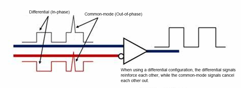
Definition of Common-Mode vs Differential Signals
A differential signal is what you want.
It is the voltage difference between two inputs.
A common-mode signal is what you do not want.
It appears equally on both inputs—noise, hum, or ground shift.
Good amplifiers amplify the difference and reject the common part.
Mathematical Definition of CMRR
CMRR compares how much differential signal is amplified versus how much common-mode signal leaks through.
| Term | Meaning |
|---|---|
| Ad | Differential gain |
| Acm | Common-mode gain |
| CMRR | Ad / Acm |
CMRR Formula and dB Expression
CMRR is almost always stated in decibels:
[
\text{CMRR(dB)} = 20 \log_{10}\left(\frac{A_d}{A_{cm}}\right)
]
Higher is better. Always.
Intuitive Explanation
Imagine two people talking in a noisy room.
CMRR is the listener’s ability to hear the difference between voices while ignoring the crowd.
Simple Numerical Example
- Differential gain = 1000
- Common-mode gain = 0.1
CMRR = 10,000 → 80 dB
That means common-mode noise is reduced by 10,000×.
Why CMRR Matters in Analog Circuit Design
Signal Accuracy and Noise Immunity
Low-level signals drown easily.
A poor CMRR lets noise sneak in and distort results.
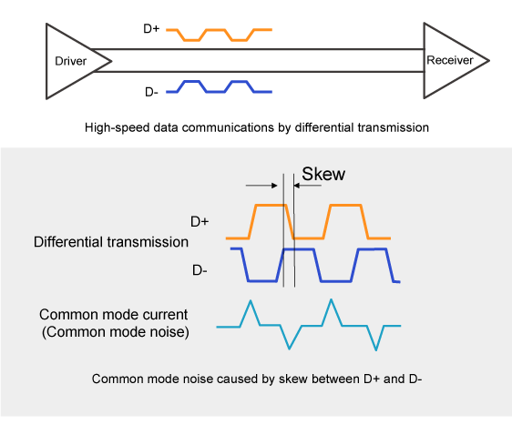
Power-Line Noise, EMI, and Ground Offset
The most common enemies:
- 50/60 Hz mains hum
- EMI from motors and radios
- Ground potential differences
All are common-mode problems.
Real-World Examples
- Strain gauges near motors
- Medical sensors on human bodies
- Industrial ADC inputs across long cables
In each case, CMRR separates signal from chaos.
DC CMRR vs AC CMRR
What Is DC CMRR?
DC CMRR measures rejection at 0 Hz.
It reflects resistor matching and input stage symmetry.
What Is AC CMRR?
AC CMRR changes with frequency.
As frequency rises, rejection usually falls.


Why CMRR Degrades at High Frequency
- Parasitic capacitance
- Internal transistor imbalance
- Limited loop gain
Physics always wins.
Which Applications Care Most?
| Application | DC CMRR | AC CMRR |
|---|---|---|
| Load cells | Critical | Moderate |
| Audio | Moderate | Critical |
| High-speed ADCs | Low | Critical |
CMRR vs Frequency: The Hidden Trade-Off
Internal Op-Amp Limits
CMRR is not flat.
Datasheets often show a steep drop beyond 1 kHz or 10 kHz.
Interpreting Datasheet Curves
Look for:
- Test frequency
- Common-mode voltage level
- Gain setting
Never trust a single number.
Most Affected Applications
- Switching power environments
- Long cable sensors
- High-resolution data acquisition
CMRR vs Related Specifications
CMRR vs PSRR
Both reject noise—but from different places.
| Spec | Rejects Noise From |
|---|---|
| CMRR | Inputs |
| PSRR | Power rails |
Precision systems need both.
CMRR vs Gain
Higher closed-loop gain can hide poor CMRR.
But the error is still there—just scaled.
Gain Error vs Common-Mode Error
Gain errors scale the signal.
CMRR errors corrupt it.
That difference matters.
Input Common-Mode Range and Its Effect on CMRR
What Is Input Common-Mode Range?
It is the voltage window where the input stage works correctly.
CMRR Near the Rails
Near supply rails:
- Input transistors saturate
- Matching degrades
- CMRR collapses
Rail-to-Rail Trade-Offs
Rail-to-rail inputs offer flexibility.
They often sacrifice peak CMRR.
Read datasheets carefully.
What Determines CMRR Performance?
Internal Resistor Matching
CMRR lives and dies by matching.
A 0.1% mismatch can ruin a 100 dB spec.
Why Instrumentation Amplifiers Win
They use:
- Laser-trimmed resistors
- Symmetrical architectures
Result: 110–130 dB CMRR is common.


External Resistor Matching
In discrete designs:
- Use 0.01% resistors
- Match temperature coefficients
- Place resistors close together
External and PCB-Level Factors That Degrade CMRR
Source Impedance Imbalance
Even perfect amplifiers fail if sources differ.
Equalize source resistance whenever possible.
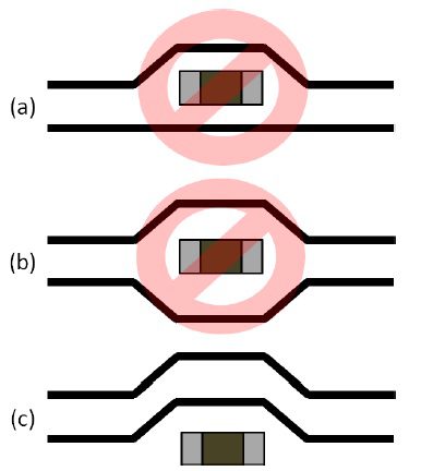
Wiring, Cables, and Connectors
- Twisted pairs
- Equal length traces
- Shielding
Small asymmetries matter.
PCB Layout Strategy

Best practices:
- Differential routing
- Solid ground planes
- No ground loops
Layout can destroy datasheet performance.
Typical CMRR Values and Benchmarks
| Device Type | Typical CMRR |
|---|---|
| General op-amp | 70–90 dB |
| Precision op-amp | 100–120 dB |
| Instrumentation amp | 110–130 dB |
| Medical-grade systems | ≥120 dB |
Higher standards demand higher rejection.
How to Evaluate CMRR When Choosing ICs
Typical vs Minimum Specs
Always design to minimum, not typical.
Temperature and Voltage Conditions
CMRR degrades:
- At temperature extremes
- Near supply limits
Check the fine print.
Datasheet Red Flags
- Single-frequency specs
- “Typical only” curves
- Unrealistic test conditions
If it looks too good, it is.
Practical Design Tips and Final Takeaways
Proven Ways to Improve CMRR
- Balance source impedances
- Use instrumentation amplifiers
- Match resistors tightly
- Route symmetrically
- Filter common-mode noise early
Common Mistakes
- Ignoring AC CMRR
- Trusting one-number specs
- Poor grounding
Final Thought
CMRR is not just a number.
It is a system-level promise.
As a classic engineering proverb says:
“What you don’t measure—and reject—will measure you later.”
Design for CMRR early.
Your signals will thank you.
