
Rail-to-Rail Input and Output Explained: What Engineers, Buyers, and Decision-Makers Need to Know
“What gets measured gets managed. What gets misunderstood gets misdesigned.”
— paraphrased from Peter Drucker
Rail-to-rail sounds simple. It is not.
For engineers, it affects accuracy.
For buyers, it affects cost.
For decision-makers, it affects product success.
This guide cuts through marketing language and explains what rail-to-rail really means, where it works, and where it quietly fails. Short sentences. Clear ideas. No fluff.
What Does “Rail-to-Rail” Mean in Analog ICs?
Rail-to-rail describes how close a signal can get to the power supply rails of an analog IC.
Those rails define the usable electrical world of the device. Everything else is headroom.
Understanding Power Supply Rails (V+ and V−)
- V+ is the positive supply.
- V− is the negative supply (or ground in single-supply systems).
In a 3.3 V single-supply design:
- V+ = 3.3 V
- V− = 0 V
Any signal outside this range risks distortion, clamping, or damage.
Rail-to-Rail vs. Signal Headroom in Real Designs
Rail-to-rail does not mean zero loss.
Every transistor needs voltage to operate.
That voltage is called headroom.
Even “rail-to-rail” devices usually stop:
- 10–200 mV short of the rails
- More under load
- More at high temperature
Why Rail-to-Rail Became Critical in Low-Voltage Systems
As supply voltages dropped from ±15 V to 5 V, then to 3.3 V and below, lost headroom became deadly.
- IoT devices run on coin cells
- Sensors output millivolts
- ADCs need full-scale swing
Rail-to-rail moved from nice-to-have to mandatory.
Rail-to-Rail Input vs. Rail-to-Rail Output (Explicit Clarification)
This is where confusion starts.
| Term | What It Actually Means |
|---|---|
| Rail-to-Rail Input (RRI) | Input common-mode range includes both rails |
| Rail-to-Rail Output (RRO) | Output swing reaches close to both rails |
| True RRI/RRO | Both input and output approach rails |
Critical truth:
👉 RRI does not imply RRO.
👉 RRO does not imply RRI.
Many datasheets blur this line. Engineers pay the price.
Single-Supply vs. Dual-Supply Rail-to-Rail Behavior
Rail-to-Rail Performance in Single-Supply Designs
Single-supply systems depend on rail-to-rail behavior.
Why?
- Ground is often the signal reference
- No negative voltage exists
- Sensors output near 0 V
Without RRI, the amplifier goes blind near ground.
Why Rail-to-Rail Matters Less in ± Dual-Supply Systems
In ±5 V systems:
- Signals float comfortably around 0 V
- Input stages stay in their linear region
- Output swing has room
Rail-to-rail still helps—but it is not critical.
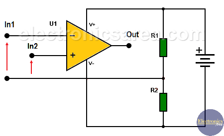
Virtual Ground and Mid-Supply Biasing
Designers often create a virtual ground at mid-supply.
This works. But it adds:
- Noise
- Offset
- Startup complexity
Rail-to-rail input removes the need.
Rail-to-Rail Input (RRI) Explained
Definition: Input Common-Mode Voltage Range
RRI means the input common-mode voltage range includes:
- V−
- V+
Sometimes slightly beyond, sometimes not guaranteed.
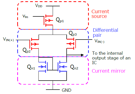
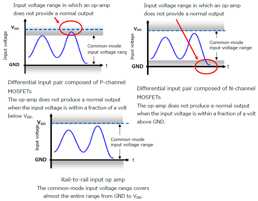
Input Stage Architectures Used in RRI Op-Amps
NMOS + PMOS Differential Pair Switching
Most RRI designs use two input pairs:
- NMOS pair near V+
- PMOS pair near V−
As input voltage moves, the device switches pairs.
Complementary Input Stages and the Crossover Region
The switch is not perfect.
The overlap region causes:
- Offset jumps
- Noise spikes
- Distortion
This is called the crossover region.
Impact on Noise, Offset, and Distortion
Near the crossover:
- Offset voltage increases
- Input bias current changes
- THD worsens
Datasheets rarely highlight this.
Real-World RRI Limitations
Crossover Distortion and Nonlinear Regions
Precision suffers exactly where rail-to-rail is claimed.
Irony is common in analog design.
Input ESD Diodes and Protection Limits
Inputs may tolerate the rail electrically but not safely.
Absolute maximum ratings are not operating ranges.
Rail-to-Rail Output (RRO) Explained
Definition: Output Voltage Swing Near the Rails
RRO means the output can swing close to both rails.
Close is load-dependent.
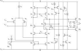
Output Stage Architectures
Class AB Push-Pull Output Stages
Most RRO designs use CMOS push-pull stages.
They save power.
They lose symmetry.
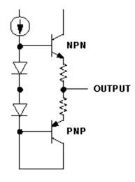
CMOS vs. Bipolar Output Stages
| Output Type | Strength | Weakness |
|---|---|---|
| CMOS | Low power | Weak drive near rails |
| Bipolar | Strong drive | Needs headroom |
Source vs. Sink Asymmetry
Many op-amps:
- Sink better than they source
- Or the reverse
Check both VOH and VOL specs.
Why “Rail-to-Rail” Never Means Exactly at the Rail
Transistors need voltage to stay on.
Zero headroom means zero control.
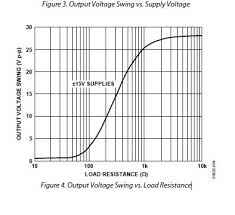
Load, Current, and Temperature Effects
Heavier load = less swing.
Higher temperature = more loss.
Worst-case matters.
Output Clamping and Saturation
Some outputs clamp softly.
Others snap hard.
This affects recovery time.
Electrical Trade-Offs of Rail-to-Rail Designs
Offset Voltage and Drift
Rail-to-rail inputs usually trade:
- Higher offset
- Higher drift
Precision suffers.
Noise Performance Near the Rails
Noise density rises near crossover.
Sensor signals feel it first.
Reduced Open-Loop Gain
Gain collapses near the rails.
Closed-loop error rises.
Stability and Phase Margin
Changing input stages changes dynamics.
Compensation is harder.
Rail-to-Rail Performance vs. Process Technology
CMOS Rail-to-Rail Op-Amps
Best for:
- Low voltage
- Low power
- Integration
Worst for:
- Noise
- High precision
Bipolar and BiCMOS Limitations
Bipolar needs voltage headroom.
BiCMOS balances both—but costs more.
Cost and Voltage Trade-Offs
Nothing is free.
Typical Applications That Truly Need Rail-to-Rail

| Application | Why Rail-to-Rail Matters |
|---|---|
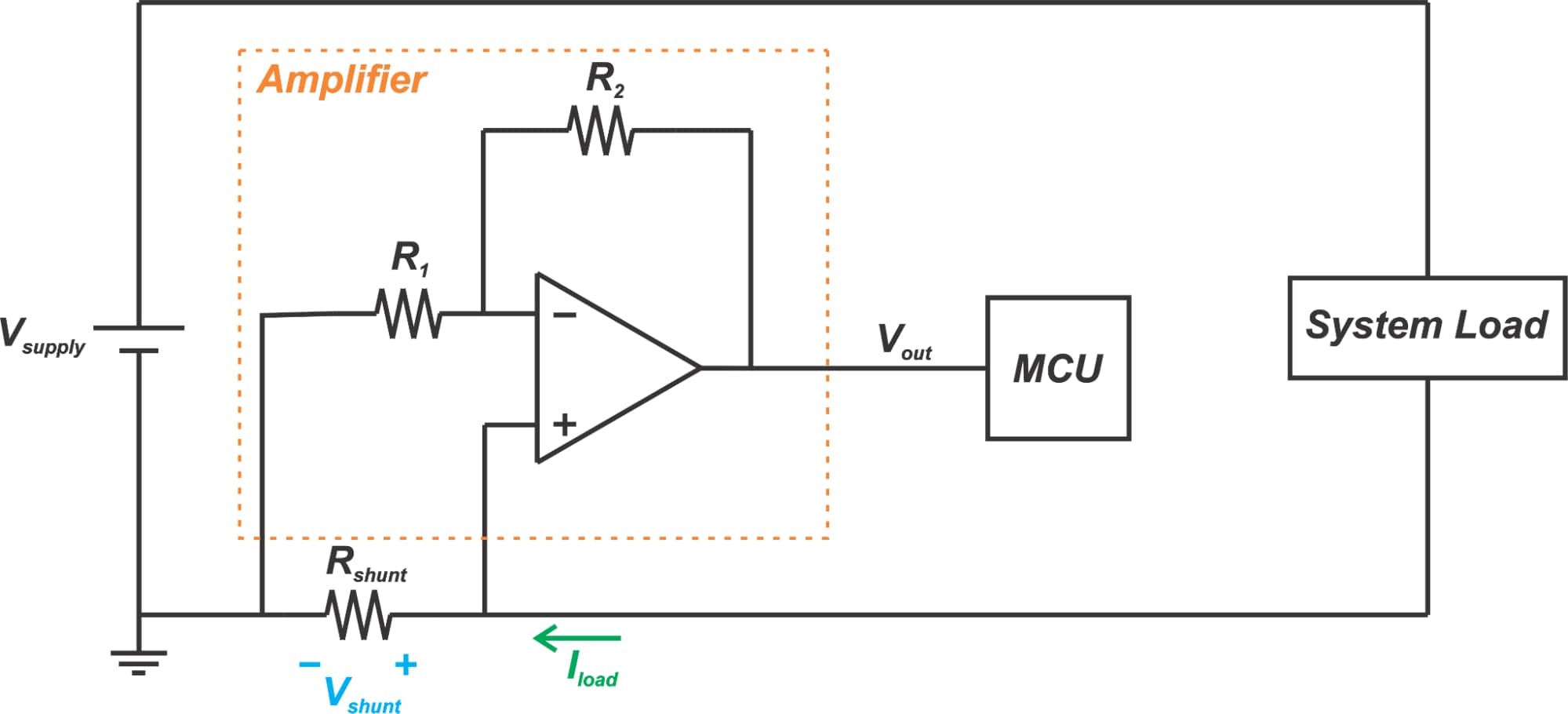
| Battery sensors | Full signal extraction |
| Current shunts | Millivolt-level sensing |
| Photodiodes | Ground-referenced currents |
| Wearables | Maximum ADC range |
Common Rail-to-Rail Design Mistakes
- Trusting marketing headlines
- Ignoring test conditions
- Designing to typical specs
- Forgetting temperature corners
“The datasheet always tells the truth. But never the whole truth.”
How to Select the Right Rail-to-Rail Solution
Key Parameters to Verify
- Input common-mode range (guaranteed)
- Output swing vs. load
- Offset and drift across temperature
- Crossover distortion behavior
Aligning with System Requirements
Do you need:
- Accuracy?
- Power efficiency?
- Full-scale ADC drive?
Pick one first.
Procurement and Lifecycle Considerations
- Second-source availability
- Process maturity
- Automotive or industrial grade stability
Final Takeaway
Rail-to-rail is not a checkbox.
It is a design philosophy.
Used correctly, it unlocks performance.
Used blindly, it hides failure.
Choose carefully.
Measure aggressively.
Design for worst case—not best hope.
