
Understanding Op Amp Basics and Applications
Operational amplifiers—op amps—sit at the heart of modern electronics. Quietly. Reliably. Everywhere. From smartphones and cars to medical devices and factory sensors, these tiny building blocks amplify, filter, compare, and condition signals that make products work.
As the saying attributed to electronics pioneer Bob Widlar goes: “Analog design is not about equations alone. It’s about understanding behavior.”
This article delivers that understanding—clearly, deeply, and practically—at a 7th-grade reading level, while still meeting expert expectations.
What Is an Operational Amplifier?


An operational amplifier is a high-gain electronic device designed to amplify the difference between two input voltages.
Short sentence. Big impact.
Core Purpose
An op amp takes a small signal and turns it into a useful signal. It does this with precision, stability, and flexibility.
Why Op Amps Matter
- They form the backbone of analog electronics
- One IC can perform dozens of functions
- They reduce cost, size, and design time
Where You See Them Today
- Audio amplifiers
- Sensor signal conditioning
- Power control loops
- Medical instrumentation
In modern products, op amps are everywhere—but rarely noticed.
Historical Background and Evolution of Op Amps


Op amps did not appear overnight.
From Vacuum Tubes to Silicon
Early op amps used bulky vacuum tubes. They were hot, large, and fragile. But they worked.
Role in Analog Computing
In the 1940s and 1950s, op amps powered analog computers. They solved equations in real time—long before digital CPUs dominated.
Rise of IC Op Amps
The invention of integrated circuits changed everything:
- Smaller size
- Lower power
- Mass production
The legendary μA741 helped standardize op amp design. From there, innovation exploded.
Basic Structure and Internal Design of Op Amps


An op amp may look simple from the outside. Inside, it’s carefully engineered.
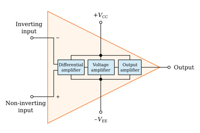
Key Terminals
- Non-inverting input (+)
- Inverting input (–)
- Output
- Power supplies
Inside the Chip
- Differential input stage
- High-gain voltage stage
- Output buffer
Each block serves one purpose: accuracy.
Ideal vs. Real Op Amps
| Parameter | Ideal Op Amp | Real Op Amp |
|---|---|---|
| Gain | Infinite | Very high |
| Input impedance | Infinite | High |
| Output impedance | Zero | Low |
| Bandwidth | Infinite | Limited |
Real-world limits define real-world design.
Ideal Op Amp Assumptions and Golden Rules
Design starts with assumptions. Then reality steps in.
Ideal Assumptions
- Infinite open-loop gain
- Zero input current
- Zero offset voltage
These simplify analysis.
The Two Golden Rules
- Inputs draw no current
- Inputs sit at the same voltage (with feedback)
These rules unlock fast circuit analysis. Break them—and math gets messy.
Open-Loop and Closed-Loop Operation
An op amp without feedback is like a car with no steering.
Open-Loop Operation
- Extremely high gain
- Tiny input differences cause saturation
- Rarely useful alone
Closed-Loop Operation
Negative feedback stabilizes everything.
Benefits include:
- Predictable gain
- Wider bandwidth
- Lower distortion
| Mode | Stability | Practical Use |
|---|---|---|
| Open-loop | Poor | Comparators |
| Closed-loop | Excellent | Amplifiers |
Feedback is not optional. It’s essential.
Feedback in Op Amp Circuits
Feedback defines behavior.
Negative Feedback
- Improves accuracy
- Reduces sensitivity to variations
- Increases bandwidth
Positive Feedback
- Used in comparators
- Enables hysteresis
- Can cause oscillation
Trade-Offs
More feedback means:
- Lower gain
- Better stability
Less feedback means:
- Higher gain
- Higher risk
Smart designers balance both.
Common Op Amp Configurations and Applications


Op amps are functional chameleons.
Common Configurations
| Configuration | Purpose | Typical Use |
|---|---|---|
| Inverting | Signal gain with phase flip | Audio |
| Non-inverting | High input impedance | Sensors |
| Voltage follower | Buffering | ADC inputs |
| Differential | Noise rejection | Industrial signals |
Application Circuits
- Summing amplifiers (mix signals)
- Integrators (control systems)
- Differentiators (edge detection)
- Active filters (noise control)
One chip. Many jobs.
How to Choose the Right Op Amp for Your Design
Choosing wrong costs money. Choosing right saves projects.
Key Selection Criteria
- Supply voltage range
- Bandwidth and slew rate
- Noise and offset voltage
- Temperature stability
Practical Considerations
- Availability
- Long-term lifecycle
- Vendor support
As IEEE design guides emphasize: “The best component is not the fastest—but the most appropriate.”
Why Understanding Op Amps Matters for Decision Makers
Op amps are not just for engineers.
For Engineers
- Faster debugging
- Cleaner designs
- Fewer redesigns
For Product Managers
- Better performance trade-offs
- Shorter development cycles
For Executives and Buyers
- Reduced BOM cost
- Lower supply-chain risk
- Improved reliability
Knowledge is leverage. In electronics, op amps provide it.
Final Thoughts
Operational amplifiers are small—but powerful.
Simple—but deep.
Old—but still evolving.
Mastering op amp basics is not optional for modern electronics. It is foundational.
And as the old engineering proverb says:
“You don’t design circuits. You design behavior.”
Understanding op amps is how that behavior begins.
