

MP1584 Buck Converter Module for Efficient and Compact Power Design
Modern electronics demand small size, high efficiency, and rock-solid reliability. Power design is no longer an afterthought—it defines system stability and lifespan. Among countless DC-DC solutions, the MP1584 buck converter module stands out as a compact yet powerful workhorse.
This guide delivers expert-level depth, clear explanations, and practical design insight—while staying readable. Short sentences. Clear logic. Real engineering value.
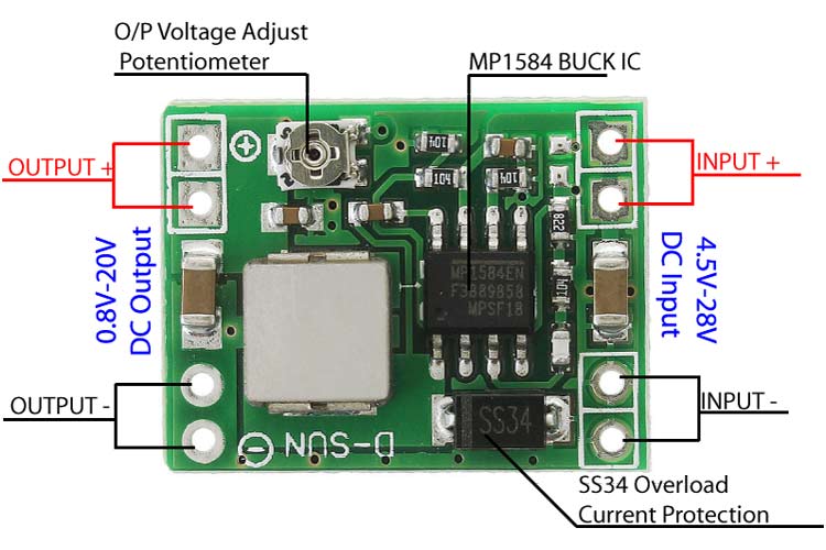
What Is the MP1584 Buck Converter Module?
The MP1584 is a high-frequency step-down (buck) DC-DC converter.
Its job is simple but critical: convert higher DC voltage into a lower, stable DC voltage with minimal loss.
Unlike bulky linear regulators, the MP1584 uses switch-mode regulation. Energy is transferred efficiently through an inductor, not burned as heat.
Why engineers like it:
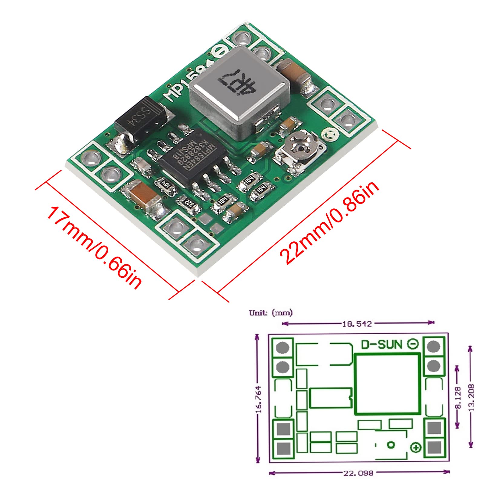
- Tiny module footprint
- High efficiency (often >90%)
- Adjustable output voltage
- Low cost and wide availability
“Efficiency is doing better what is already being done.” — Peter Drucker
The MP1584 embodies that principle in power electronics.
Core Features That Define the MP1584
At its core, the MP1584 integrates a high-speed switching regulator with internal power MOSFETs.
Key highlights
- Input voltage range: 4.5V to 28V
- Adjustable output: 0.8V to ~24V
- Switching frequency: ~1.5 MHz
- Peak current: up to 3A (theoretical)
High switching frequency allows:
- Smaller inductors
- Smaller capacitors
- Compact PCB layout
Built-in protections include:
- Over-current protection (OCP)
- Thermal shutdown
- Under-voltage lockout (UVLO)
These features reduce external components and simplify design.
Real-World Electrical Performance (Not Just Datasheet Numbers)
Datasheets promise perfection. Reality demands caution.
Continuous Current Reality
Although often marketed as a 3A module, real-world continuous current is lower.
| Cooling Condition | Safe Continuous Output |
|---|---|
| No airflow | 1.2–1.5A |
| Good PCB copper | 1.8–2.0A |
| Heatsink + airflow | 2.5A (short duration) |
Regulation Performance
| Parameter | Typical Performance |
|---|---|
| Line regulation | ±1% |
| Load regulation | ±1–2% |
| Output ripple | 20–50 mV (with good caps) |
Noise remains low for most digital systems.
Sensitive RF or ADC circuits may need extra LC filtering.
Input–Output Design Examples (Practical Use Cases)


12V → 5V Conversion
Common in automotive and embedded systems.
- Input: 12V nominal (up to 14.4V)
- Output: 5V
- Load: MCU, sensors, displays
- Efficiency: ~90–93%
24V Industrial Rails
Works well with PLCs and control cabinets.
- Input: 18–28V
- Output: 5V or 3.3V
- Add TVS diode for surge protection
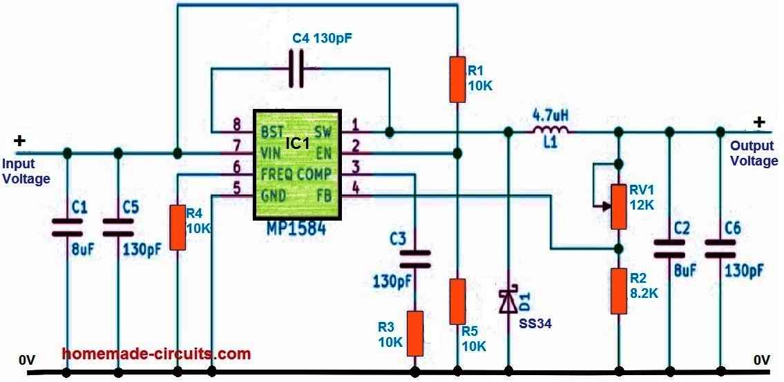
Output Voltage Formula
The MP1584 uses a feedback divider:
Vout = 0.8 × (1 + R1 / R2)
Small changes matter. Adjust slowly. Measure often.
Thermal Management and Heat Dissipation
Heat is the silent killer of power modules.
The MP1584 IC can tolerate high junction temperatures, but modules are small. Heat builds fast.
Thermal Design Tips
- Use thick copper pours under the module
- Avoid enclosing the module tightly
- Add airflow when current exceeds 1.5A
- Consider a small adhesive heatsink
| Temperature Zone | Reliability Impact |
|---|---|
| <70°C | Excellent |
| 70–100°C | Acceptable |
| >120°C | Risky |
Thermal shutdown protects the chip—but frequent shutdowns shorten lifespan.
Protection and Safety Features
Protection is not optional. It’s essential.
Built-In Safeguards
- Over-current protection: Limits damage during overload
- Short-circuit protection: Auto recovery after fault removal
- UVLO: Prevents unstable startup
- Thermal shutdown: Saves silicon from destruction
These features make MP1584 modules safe for prototyping and robust for production.
Still, protection is not immunity. Respect limits.
Assembly, Adjustment, and Usage Best Practices
Mistakes here are common—and costly.
Safe Adjustment Steps
- Power the module without load
- Measure output with a multimeter
- Adjust the potentiometer slowly
- Re-measure after every turn
Common Errors to Avoid
- Connecting load before adjustment
- Reversing polarity
- Using thin wires at high current
- Ignoring startup surge current
“Measure twice. Power once.” — Every good engineer
Advantages and Typical Applications
The MP1584 module shines where space, cost, and efficiency matter.
Key Advantages
- Reduced BOM cost
- Minimal design effort
- High efficiency at moderate loads
- Compact size for dense layouts
Typical Applications
- Arduino and Raspberry Pi projects
- IoT gateways and sensors
- Industrial controllers
- Automotive accessories
- Battery-powered systems (with care)
| Application | Suitability |
|---|---|
| Prototyping | Excellent |
| Mass production | Good |
| High-power systems | Limited |
MP1584 vs Other Buck Converter Modules
| Feature | MP1584 | LM2596 |
|---|---|---|
| Switching frequency | ~1.5 MHz | ~150 kHz |
| Size | Very small | Large |
| Efficiency | Higher | Lower |
| Output current | Lower | Higher |
When to choose MP1584:
Compact designs. Low to medium current. Modern layouts.
When not to:
High-power rails above 3A continuous.
Final Thoughts: Is the MP1584 the Right Choice?
The MP1584 buck converter module is not magic.
It is smart engineering in a small package.
Use it where:
- Space is limited
- Efficiency matters
- Current is reasonable
- Design time is short
Respect thermal limits. Adjust carefully.
Do that—and the MP1584 will reward you with stable, efficient power for years.
Power done right is invisible.
And that’s exactly the point.
