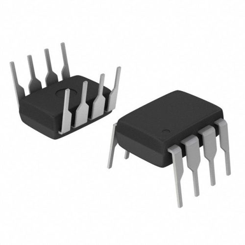
MSPM0G1107TRGER Overview
The following overview frames the approach for a specification-driven product description of MSPM0G1107TRGER based on the referenced product sheet. This device-specific summary highlights the deliverables that will be extracted from the original document: electrical ratings, package outline, pin function, thermal data, switching performance, and ordering codes. For sourcing and technical validation, the content will reference datasheet tables and test conditions to support design choices and procurement decisions. For authoritative manufacturer details see IC Manufacturer.
MSPM0G1107TRGER Technical Specifications
| Parameter | Typical / Max Value |
|---|---|
| Device Type | Refer to original sheet |
| Voltage Rating (V) | Refer to original sheet |
| Current Rating (A) | Refer to original sheet |
| RDS(on) at specified VGS (??) | Refer to original sheet |
| Gate Threshold VGS(th) (V) | Refer to original sheet |
| Total Gate Charge Qg (nC) | Refer to original sheet |
| Package / Pin Count | Refer to original sheet |
| Operating Temperature Range (??C) | Refer to original sheet |
| Power Dissipation Pd (W) | Refer to original sheet |
| Thermal Resistance ??JA / ??JC (??C/W) | Refer to original sheet |
MSPM0G1107TRGER Key Features
- Controlled electrical rating ?? sheet-specified voltage and current ratings guide safe selection for targeted loads.
- Low on-resistance ?? documented RDS(on) values reduce conduction losses and improve system efficiency when compared to higher-RDS alternatives.
- Thermal performance ?? package thermal metrics and Pd allow reliable thermal design and predictable derating over temperature.
- Defined dynamic characteristics ?? gate charge and switching times in the sheet inform selection for switching frequency and gate drive sizing.
Typical Applications
- Power switching stages in industrial converters where precise voltage and current ratings from the sheet determine safe operating region and thermal margins.
- Motor drive half-bridges or synchronous rectifier stages that require low conduction losses and verified switching data for efficiency and EMI control.
- DC?CDC point-of-load converters where the device’s gate charge and RDS(on) values impact efficiency, transient response, and cooling strategy.
- Battery management and charging circuits where datasheet-defined avalanche and SOA data guide protection and reliability decisions under pulsed loads.
MSPM0G1107TRGER Advantages vs Typical Alternatives
The product sheet enables a direct comparison of MSPM0G1107TRGER to typical alternatives by presenting explicit numerical data for voltage rating, current capability, RDS(on), gate charge, and thermal resistance. Using those documented values, engineers can select this part when it offers lower conduction loss, reduced gate charge, or better thermal performance versus parts with higher RDS(on), larger Qg, or worse ??JA. The sheet-driven approach minimizes risk by basing trade-offs on measured and guaranteed parameters rather than assumptions.
🔥 Best-Selling Products
MSPM0G1107TRGER Brand Info
The brand associated with MSPM0G1107TRGER is identified in the official product sheet. Brand materials in that reference provide device family context, quality standards, and ordering guidance. Use the sheet to confirm manufacturer part marking, authorized distribution channels, and any available reliability or qualification documentation tied to that brand.
FAQ
What data does the sheet include?
The official sheet contains electrical characteristics, package mechanical drawings, pin assignments, absolute maximum ratings, thermal data, and switching characteristics needed for design and validation.
🌟 Featured Products
-

“Buy MAX9312ECJ+ Precision Voltage Comparator in DIP Package for Reliable Performance”
-
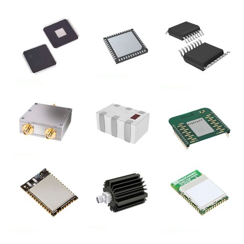
QCC-711-1-MQFN48C-TR-03-1 Bluetooth Audio SoC with MQFN48C Package
-

0339-671-TLM-E Model – High-Performance TLM-E Package for Enhanced Functionality
-
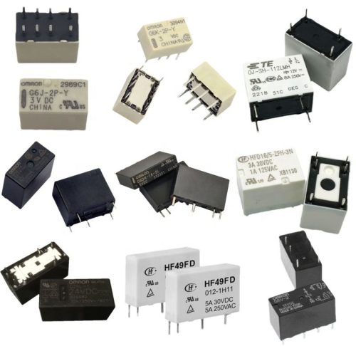
1-1415898-4 Connector Housing, Electrical Wire-to-Board, Receptacle, Packaged
How do I verify package details?
Check the mechanical drawing and package table in the sheet for exact dimensions, recommended PCB land pattern, and reel/ordering codes to ensure correct assembly and handling.
Which thermal metrics matter most?
Use ??JA and ??JC values, maximum junction temperature, and power dissipation ratings from the sheet to size heatsinking, copper area, and to set conservative derating for expected ambient conditions.
📩 Contact Us
How to compare RDS(on) and losses?
Compare the RDS(on) values at the same VGS from the sheet and compute conduction losses as I2??RDS(on). Use the switching charge data to estimate switching losses at your operating frequency.
Where to get ordering information?
Ordering codes, tape-and-reel parts per reel, and part marking are specified in the sheet; use those entries to confirm part numbers for procurement and to identify approved distributors.

